Form No. 3395-143 Rev A Base 62in and 72in Mower Groundsmaster® 3400 Traction Unit Model No. 30645—Serial No. 315000001 and Up Model No. 30646—Serial No. 315000001 and Up Register at www.Toro.com.
This manual uses 2 words to highlight information. Important calls attention to special mechanical information and Note emphasizes general information worthy of special attention. WARNING CALIFORNIA Proposition 65 Warning This product contains a chemical or chemicals known to the State of California to cause cancer, birth defects, or reproductive harm. This product complies with all relevant European directives. For details, please see the Declaration of Incorporation (DOI) at the back of this publication.
Contents Safety Safety ........................................................................... 3 Safe Operating Practices........................................... 3 Toro Mower Safety .................................................. 4 Safety and Instructional Decals ................................. 6 Setup ............................................................................ 7 1 Installing a Completion Kit .................................... 7 2 Installing the Castor Wheel Assemblies .....
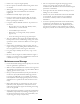
• Replace faulty silencers/mufflers. • Check that operator's presence controls, safety switches • • • Lightning can cause severe injury or death. If lightning and shields are attached and functioning properly. Do not operate unless they are functioning properly. Before using, always visually inspect to see that the blades, blade bolts, and cutting assembly are not worn or damaged. On multi-bladed machines, take care as rotating 1 blade can cause other blades to rotate.
• Do not overspeed the engine by changing governor • Know how to stop the engine quickly. • Do not operate the machine while wearing tennis shoes settings. To ensure safety and accuracy, have an Authorized Toro Distributor check the maximum engine speed with a tachometer. or sneakers. • Wearing safety shoes and long pants is advisable and required by some local ordinances and insurance regulations. • The engine must be shut off before checking the oil or • Handle fuel carefully. Wipe up any spills.
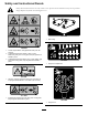
Safety and Instructional Decals Safety decals and instructions are easily visible to the operator and are located near any area of potential danger. Replace any decal that is damaged or lost. 108-1988 1. Belt routing 120-6604 1. Thrown object hazard—keep bystanders away from the machine. 2. Cutting/dismemberment hazard of hand, mower blade—stay away from moving parts, keep all guards and shields in place. 3.
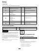
Setup Loose Parts Use the chart below to verify that all parts have been shipped. Procedure Description 1 2 3 4 5 6 Use Qty. Completion kit (sold separately) 1 Install a completion kit. Castor wheel assembly 2 Install the castor wheel assemblies. Lift-arm, right Lift-arm, left Lift cylinder pin Cylinder carriage bolt Cylinder flange nut Thrust washer Clevis pin Hairpin cotter Height-of-cut collar Clevis pin Hairpin cotter 1 1 2 2 2 4 4 2 2 2 2 No parts required – Connect the hydraulic drive.
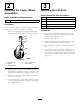
2 3 Installing the Castor Wheel Assemblies Installing the Lift Arms Parts needed for this procedure: Parts needed for this procedure: 2 Castor wheel assembly Procedure 1 Lift-arm, right 1 Lift-arm, left 2 Lift cylinder pin 2 Cylinder carriage bolt 2 Cylinder flange nut The thrust washers, spacers, and tensioning caps have been installed on the castor wheel spindles for shipping. Procedure 1.
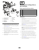
4 10 11 Installing the Cutting Unit on the Lift Arms Parts needed for this procedure: 8 7 6 2 1 3 3 2 1 4 5 Thrust washer 4 Clevis pin 2 Hairpin cotter 2 Height-of-cut collar 2 Clevis pin 2 Hairpin cotter g029329 Figure 3 1. Cylinder-carriage bolt 7. M24 washer 2. Lift-cylinder pin 8. M24 bolt 3. Cylinder-flange nut 9. Wear plate 4. Left lift arm 5. Right lift arm 4 Procedure 1. Move the cutting unit into position in front of the traction unit. 2.
WARNING 8 9 1 Hydraulic fluid escaping under pressure can penetrate skin and cause injury. • Make sure that all hydraulic fluid hoses and lines are in good condition and all hydraulic connections and fittings are tight before applying pressure to the hydraulic system. • Keep your body and hands away from pin hole leaks or nozzles that eject high pressure hydraulic fluid. • Use cardboard or paper to find hydraulic leaks.
D. Tighten each hose connection. 4. Route all hoses correctly, clean the connections, and tighten all hose lines. Retain the hose plugs and port caps for future use. 5. Use the cable ties provided to secure the hose lines. 6. Raise the operator's platform on the traction unit, and connect the cutter-valve, electrical connector (Figure 6). 1 g017952 Figure 6 1. Cutter-valve electrical port 7.
Product Overview Operation Specifications Note: Determine the left and right sides of the machine from the normal operating position. Note: Specifications and design are subject to change without notice. Width of Cut 1.575 m (62 inches) or 1.829 m (72 inches) Height of Cut Adjustable from 25 to 127 mm (1 to 5 inches) in 13 mm (1/2 inch) increments Net Weight Model 30645–210 kg (463 lbs.) Model 30646–225 kg (496 lbs.
Figure 9 1. Height-of-cut rod 2. Height-of-cut collar Figure 7 1. Tensioning cap 4. Axle-mounting holes 2. Spacers 5. Castor wheel 3. Clevis pin and hairpin cotter 10. Align the height-of-cut collar to the desired height-of-cut holes on the height-of-cut rod (Figure 10). 3. Shims Figure 8 6. Push the castor spindle through the castor arm. 7. Install the shims (as they were originally installed) and the remaining spacers onto the spindle shaft. 8. Install the tensioning cap to secure the assembly.
back of the blade plane is 13 mm (1/2 inch) higher than the front. 1. Position the machine on a level surface on the shop floor. 2. Set the cutting unit to the desired height of cut. 3. Rotate 1 blade so that it points straight forward. 4. Using a short ruler, measure from the floor to the front tip of the blade. Rotate the blade tip to the rear and measure from the floor to the tip of the blade. Figure 12 5. Subtract the front dimension from the rear dimension to calculate the blade pitch. 1. Skid 6.
4. Check for bent blades; refer to Checking for a Bent Blade (page 20). dense grass, you may have to raise the height-of-cut to the next setting. 5. Cut grass in a test area to determine if all cutting units are cutting at the same height. Mow at Proper Intervals 6. When cutting unit adjustments are still needed, find a flat surface using a 2 m (6 foot) or longer straight edge. Under most normal conditions you will need to mow approximately every 4 or 5 days.
Maintenance Important: The fasteners on the covers of this machine are designed to remain on the cover after removal. Recommended Maintenance Schedule(s) Maintenance Service Interval Maintenance Procedure After the first 10 hours • Torque the blade bolts. Before each use or daily • Check the blades. Every 50 hours • • • • • Lubricate the grease fittings. Check the gearbox-oil level. Torque the blade bolts. Check the blade-drive-belt adjustment. Clean under the cutting-unit belt-covers.
2 4 • 2 lift-arm pivots, front (Figure 17). 3 1 8 10 9 7 g017954 5 Figure 17 g017956 6 Figure 19 • 2 lift-arm pivots, rear (Figure 18). 1. Lift-arm latches 6. Lift-arm pads 2. Hairpin cotter 7. Clevis pin 3. Clevis pin 8. Hairpin cotter 4. Height-of-cut collar 5. Height-of-cut rod 9. Right lift arm 10. Right caster arm 3. Pivot the deck until the clevis pin will fit through the hole in the right castor arm and secure it to the right lift arm.
2. Remove the hairpin cotter and clevis pin securing the height-of-cut rod to the rear of the cutting unit (Figure 20). Remove the height-of-cut collars. 1 2 3 3 g017959 Figure 22 g017957 2 1 Figure 20 6. Raise the lift arms, latch them in the raised position, and roll the cutting unit away from the traction unit. Turn off the ignition switch. 3. Hairpin cotter and clevis pin 1. Height-of-cut rod 2. Height-of-cut collar CAUTION 3.
10 bushings will wear. To check the bushings, move the castor fork back and forth and from side to side. If the castor spindle is loose inside the bushings, the bushings are worn; replace them as follows: 8 9 1 4 1. Raise the cutting unit so that the wheels are off of the floor. Latch the cutting unit so that it cannot accidentally fall. 7 6 5 2. Remove the tensioning cap, spacer(s), and thrust washer from the top of the castor spindle. 3 3. Pull the castor spindle out of the mounting tube.
3. Rotate the opposite end of the blade forward. Measure between the cutting unit and cutting edge of the blade at the same position as in step 2. Note: The difference between the dimensions obtained in steps 2 and 3 must not exceed 3 mm (1/8 inch). If the dimension exceeds 3 mm (1/8 inch), replace the blade because it is bent; refer to Removing and Installing the Blade (page 20). Removing and Installing the Blade Service Interval: After the first 10 hours Figure 25 1. Castor wheel 3. Bearing (2) 2.
Inspecting and Sharpening the Blade(s) 3. Replace the blade if you detect wear; refer to Removing and Installing the Blade (page 20). 4. Remove the blades and sharpen them on a grinder. Service Interval: Before each use or daily Important: Sharpen only the top side of the cutting edge and maintain the original cutting angle to ensure sharpness (Figure 29). The blade will remain balanced if the same amount of metal is removed from both cutting edges.
1 add shims between the spindle housing and the bottom of the cutting unit. 11. Remove the bolts, flat washers, lock washers, and nuts from the outer spindle in the area where the shims must be added. 2 12. To raise or lower the blade, add a shim, Part No. 3256-24, between the spindle housing and the bottom of the cutting unit. 13. Continue to check the alignment of the blades and add shims until the tips of the blades are within the required dimension.
Notes: 23
Notes: 24
Notes: 25
Declaration of Incorporation Model No. Serial No.
International Distributor List Distributor: Country: Phone Number: Distributor: Phone Number: 57 1 236 4079 Colombia Japan 81 3 3252 2285 Czech Republic 420 255 704 220 420 255 704 Slovakia 220 Argentina 54 11 4 821 9999 Russia 7 495 411 61 20 Ecuador 593 4 239 6970 Finland 358 987 00733 Agrolanc Kft Balama Prima Engineering Equip. B-Ray Corporation Hungary Hong Kong Korea 36 27 539 640 852 2155 2163 82 32 551 2076 Maquiver S.A. Maruyama Mfg. Co. Inc. Mountfield a.s.
Toro General Commercial Product Warranty A Two-Year Limited Warranty Conditions and Products Covered The Toro Company and its affiliate, Toro Warranty Company, pursuant to an agreement between them, jointly warrant your Toro Commercial product (“Product”) to be free from defects in materials or workmanship for two years or 1500 operational hours*, whichever occurs first. This warranty is applicable to all products with the exception of Aerators (refer to separate warranty statements for these products).