
Operator's Manual

g017950
1
2
3
4
5
6
7
8
9
10
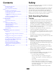
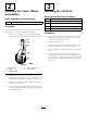
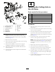
Figure4
1.Lift-arm6.Clevispin
2.Castor-armbracket
7.Hairpincotter
3.Height-of-cutrod8.Height-of-cutcollar
4.Lift-armpads9.Clevispin
5.Thrustwashers10.Hairpincotter
5
ConnectingtheHydraulic
Drive
NoPartsRequired
Procedure
Important:Foryoursafetythecutter-valve,electrical
connectorhasbeendisconnectedtodisablethe
operationofthecutterdrive.Connecttheelectrical
connectorafterallhoselineconnectionshavebeen
madecorrectly.
WARNING
Hydraulicuidescapingunderpressurecan
penetrateskinandcauseinjury.
•Makesurethatallhydraulicuidhosesand
linesareingoodconditionandallhydraulic
connectionsandttingsaretightbefore
applyingpressuretothehydraulicsystem.
•Keepyourbodyandhandsawayfrompin
holeleaksornozzlesthatejecthighpressure
hydraulicuid.
•Usecardboardorpapertondhydraulicleaks.
•Safelyrelieveallpressureinthehydraulicsystem
beforeperforminganyworkit.
•Seekimmediatemedicalattentionifuidis
injectedintoyourskin.
Note:Somehydraulicuidlossmayoccur.
1.Turnoffthecuttingunits,lowerthem,stoptheengine,
engagetheparkingbrake,andremovetheignitionkey.
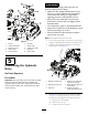
2.Cleantheareasaroundthehydraulicportsandthe
hydraulic-hoseends(Figure5).
g017951
1
2
3
4
5
6
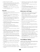
Figure5
1.Blankingcap(5/8inch)4.Drainport(tocutting-unit
valveteeonCDport)
2.Blankingcap(3/8inch)5.Returnport(tocutting-unit
valveM2port)
3.Cableties6.Pressureport(from
cutting-unitvalveM1port)
3.Identifythe3hydraulichoselinesandports.Refer
toFigure5fortheappropriateportforeachhose.
Performthefollowingprocessforeachconnection:
A.Removethehose-lineplug.
B.Removetheportcap.
C.Connectthehosetotheport.
10