
Operator's Manual


g029329
1
2
3
4
5
1
2
3
6
7
8
9
10
11
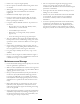
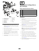
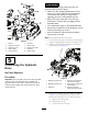
Figure3
1.Cylinder-carriagebolt
7.M24washer
2.Lift-cylinderpin
8.M24bolt
3.Cylinder-angenut
9.Wearplate
4.Leftliftarm
10.Nut
5.Rightliftarm
11.Armpin
6.Carriagebolt
6.Mounttheliftarmstothetractionunitwiththe
bendspositionedoutward,andsecurethemusingthe
previouslyremovedlift-armpivotpins,carriagebolts,
andnuts(Figure3).
7.Raiseandsecuretheliftarms.
8.Turnonthetraction-unitignitionandmovethecutting
unittotheFLOATposition.
9.Securethelift-cylinderstotheliftarmsusingthe
suppliedliftcylinderpins,carriagebolts,andnuts.
10.Turnoffthetractionunit,andlowerandsecurethe
operatorplatform.
11.Installthe2frontwheelsandplacethemachineback
ontotheoor.
4
InstallingtheCuttingUniton
theLiftArms
Partsneededforthisprocedure:
4Thrustwasher
4
Clevispin
2Hairpincotter
2
Height-of-cutcollar
2
Clevispin
2Hairpincotter
Procedure
1.Movethecuttingunitintopositioninfrontofthe
tractionunit.
2.Turnonthetractionunitignitionandmovethecutting
unittotheFLOATposition.
3.Pushalift-armdownuntiltheholesinthelift-armline
upwiththeholesinthecastor-armbracketandthe
height-of-cutrodisabletobeinsertedintothelift-arm
pads(Figure4).
4.Securethelift-armtothecastor-armwith2thrust
washers,aclevispinandahair-pincotter.
Note:Positionthethrustwashersbetweenthelift-arm
andthecastor-armbracket(Figure4).Insertendof
cotterpinintotheslotinthecastor-armtabtoretain
cotterpin.
5.Repeatstep3and4ontheoppositelift-arm.
6.Startthetractionunitandraisethecutting-unit.
7.Pushdownontherearofthecuttingunitandinsert
theheight-of-cutrodsthroughthelift-armpads.
8.Installtheheight-of-cutcollarsontotheheight-of-cut
rodsandsecurethemwiththeclevispinsandhairpin
cotters(Figure4).
9.Lowerthedeckandswitchthetraction-unitignition
switchtotheOFFposition.
9