Form No. 3439-307 Rev B CT2240 Compact Triple 4-Wheel Drive Turf Mower Model No. 30654—Serial No. 405600000 and Up Register at www.Toro.com.
This product complies with all relevant European directives; for details, please see the separate product specific Declaration of Conformity (DOC) sheet. Model No. Serial No. This manual identifies potential hazards and has safety messages identified by the safety-alert symbol (Figure 2), which signals a hazard that may cause serious injury or death if you do not follow the recommended precautions.
Contents Engine Maintenance ........................................... 38 Engine Safety ................................................... 38 Checking the Engine Overheat Warning System.......................................................... 38 Servicing the Air Cleaner .................................. 38 Servicing the Engine Oil and Filter .................... 39 Fuel System Maintenance ................................... 40 Draining the Fuel Tank ......................................
Safety Storage Safety.................................................. 51 Preparing the Traction Unit ............................... 51 Preparing the Engine ........................................ 52 Troubleshooting ...................................................... 53 This machine has been designed in accordance with EN ISO 5395. General Safety This product is capable of amputating hands and feet and of throwing objects.
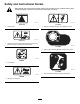
Safety and Instructional Decals Safety decals and instructions are easily visible to the operator and are located near any area of potential danger. Replace any decal that is damaged or missing. decal70-13-072 decal111-0773 70-13-072 111-0773 1. Jacking point 1. Warning—crushing of fingers, force applied from side. decal70-13-077 70-13-077 1. Warning—shut off the engine and remove the ignition key before releasing or operating the safety latches. decal111-3344 111-3344 1.
decal111-3901 111-3901 1. Transmission fluid—read the Operator's Manual. decal111-3566 111-3566 1. Falling, crushing hazard—ensure that the operator platform latch is engaged before operating. decal111-3902 111-3902 1. The fan can cut your hand; warning 2. Hot surfaces; read the Operator's Manual. decal111-3567 111-3567 1. Pedal operation to control machine direction decal111-3658 111-3658 1. Cutterhead 2. Latch 3.
decal134-1807 134-1807 1. Slope indicator 7. Raise 2. Right cutting unit controls 8. Fast 9. Engine speed 3. Center cutting unit controls 4. Left cutting unit controls 10. Slow 5. Lower/float 6. Transport 11.
decal111-8098 111-8098 Note: This machine complies with the industry standard stability test in the static lateral and longitudinal tests with the maximum recommended slope indicated on the decal. Review the instructions for operating the machine on slopes in the Operator’s Manual as well as the conditions in which you would operate the machine to determine whether you can operate the machine in the conditions on that day and at that site.
decal111-7249 111-7249 1. Daily service interval 6. Check hydraulic fluid level 2. 50 hour service interval 7. Check fuel level 3. Check the tire pressure 8. Check engine oil level 4. Check all nuts and bolts for proper tightness 9. Check operation of seat switch 5. Check all hoses for leaks 10. Check air filter element 11. Check cutting unit setting 16. Lubrication points for daily interval 12. Check engine coolant level 17. Lubrication points for 50 hour interval 13.
Setup Media and Additional Parts Description Operator's Manual Engine owner’s manual Use Qty. 1 1 Read the manuals before operating the machine. Store all documentation in a safe place for future use. Note: Determine the left and right sides of the machine from the normal operating position.
Controls Product Overview Control Panel Components g025164 Figure 3 1. Front cutting units 4. Operator's seat 2. Control arm 5. Engine hood 3. Steering wheel 6. Rear cutting unit g014418 Figure 4 1. Parking brake switch 11. Horn button 2. Limited lift in reverse switch 12. Auxiliary 12 volt socket (supplied with a 12 V kit) 3. Hazard warning switch (supplied with lighting kit) 13. Engine-oil pressure indicator 4. Warning beacon switch 14.
g014421 Figure 7 1. Parking brake g014419 Figure 5 Emergency Brake 1. Weight transfer control In the event of service brake failure, turn the ignition off to bring the mower to a standstill. WARNING Application of the emergency brake activates front wheel brakes of the mower; while traveling, a sudden stop may cause ejection from the mower. Remain seated and hold on to the steering wheel when using the emergency brake.
Transport Latches Always raise the cutting units to the transport position and secure with the transport latches and safety locks when travelling between work areas (Figure 10). g014547 Figure 8 1. Throttle control lever Traction Pedals Forward travel: Press the forward travel pedal to increase forward travel speed. Release the pedal to reduce speed (Figure 9). g014548 Figure 10 Reverse travel: Press the reverse travel pedal to increase reverse travel speed.
g014549 Figure 11 Operator Seat WARNING Damaged operator seat mechanisms may cause the seat to become loose, which may cause you to lose control of the machine. • Never operate the mower if the operator seat mechanisms are damaged or if the seat does not remain securely in position once adjusted and locked. • Adjust the seat only when the mower is at a standstill with the parking brake engaged. Fore/Aft adjustment: The seat adjusting lever allows the operator to adjust the seat fore and aft (Figure 12).
Warning Systems Low Battery Charge Warning Light Engine Coolant Overheating Warning Light The battery charge warning light illuminates when low battery charge occurs (Figure 15). The engine coolant warning light illuminates, the horn is actuated, and the cutting units stop (Figure 13). g014553 Figure 15 1. Low battery charge warning light Low Engine-Oil Pressure Warning Light The engine-oil pressure warning light illuminates when the oil pressure is too low (Figure 16). g014551 Figure 13 1.
Ignition Key Fuel Gauge The fuel gauge shows the amount of fuel in the tank (Figure 20). 0 = Engine off I = Engine run/Auxiliary on II = Engine pre-heat III = Engine start CAUTION If you leave the key in the ignition switch, someone could accidently start the engine and seriously injure you or other bystanders. g014558 Figure 20 Remove the key from the ignition. Hour Meter The hour meter shows the total hours that the machine has been operated (Figure 21). g014556 Figure 18 1.
Cutting Unit Drive Switch Indicator Light This light illuminates when the cutting unit drive switch is in the FORWARD /REVERSE position and the ignition key is turned to position I (Figure 23). g014561 Figure 23 1.
Specifications Note: Specifications and design are subject to change without notice. Specification CT 2240 Transport width 138.0 cm (54.3 inches) Width of cut 212.0 cm (83.5 inches) Overall width 236.0 cm (92.9 inches) Length 286.0 cm (112.6 inches) Height 168.1 cm (66.2 inches) with ROPS folded 211.5 cm (83.3 inches) with ROPS in the vertical operating position Weight 1240 kg (2733 lb)* With fluids and 200 mm 6-blade cutting units Engine Kubota 19.
Performing Daily Maintenance Operation Before Operation Service Interval: Before each use or daily Before starting the machine each day, perform the Each Use/Daily procedures listed in Maintenance (page 33). Before Operation Safety General Safety Checking the Engine-Oil Level • Never allow children or untrained people to operate or service the machine. Local regulations may restrict the age of the operator. The owner is responsible for training all operators and mechanics.
CAUTION If the engine has been running, the pressurized, hot coolant can escape and cause burns. • Do not open the radiator cap when the engine is running. • Use a rag when opening the radiator cap, and open the cap slowly to allow steam to escape. The cooling system is filled with a 50/50 solution of water and permanent ethylene glycol antifreeze. g008881 Figure 24 1. Dipstick 4.
Adding Fuel DANGER In certain conditions, fuel is extremely flammable and highly explosive. A fire or explosion from fuel can burn you and others and can damage property. • Fill the fuel tank outdoors, in an open area, when the engine is cold. Wipe up any fuel that spills. • Never fill the fuel tank inside an enclosed trailer. • Never smoke when handling fuel, and stay away from an open flame or where fuel fumes may be ignited by a spark.
4. Fill the tank until the level is to the bottom of the filler neck with diesel fuel. 5. Install the fuel tank cap tightly after filling the tank. Checking the Level of the Hydraulic Fluid Service Interval: Before each use or daily—Check the level of the hydraulic fluid. Note: If possible, fill the fuel tank after each use. This will minimize possible buildup of condensation inside the fuel tank. Hydraulic Fluid Specifications The reservoir is filled at the factory with high-quality hydraulic fluid.
Front Axle 23 x 10.5 - 12 BKT turf pattern 0.7 bar (10 psi) 1.4 bar (20 psi) 1.7 bar (25 psi) Rear Axle 18 x 9.5 8 BKT turf pattern 0.7 bar (10 psi) 1.4 bar (20 psi) 1.7 bar (25 psi) 2. Move the locking latch handle toward the front of the mower as the platform nears the fully lowered position. Note: This ensures that the latch hooks clear the locking bar. 3.
• Look behind and down before backing up to be You can start the engine only with the cutting unit drive switch in the OFF position. sure of a clear path. • Use care when approaching blind corners, shrubs, WARNING trees, or other objects that may obscure your vision. Operating the machine when the operator presence controls are malfunctioning could result in personal injury. • Stop the cutting units whenever you are not mowing.
– If possible, keep the cutting units lowered to the ground while operating on slopes. Raising the cutting units while operating on slopes can cause the machine to become unstable. and use the seat belt when operating the machine with the roll bar in the raised position. • Lower a folding roll bar temporarily only when necessary. Do not wear the seat belt when the roll bar is folded down.
WARNING Contact with hot or moving parts can result in personal injury. Keep all body parts away from any hot or moving parts of the engine. g014557 Figure 29 1. Engine pre-heat indicator light WARNING An illuminated warning light could indicate a serious problem that could lead to personal injury. When the engine is operating all warning lights should be off. If a warning light illuminates, shut off the engine immediately and have the fault rectified before starting the engine.
2. To raise the cutting units, operate the lift control switches in an upward direction and hold in position 3. If the cutting unit drive switch is in the ON position the reel drive will disengage immediately. 3. Release the lift control switches when the cutting units are at the required height. Auto limited lift in reverse causes the cutting units to rise automatically to the limited lift position when reversing. They return to the floating position when returning to forward travel.
Clearing the Cutting Units WARNING Never attempt to rotate the cutting units by hand. 1. Release the valve locknut 1/2 turn counterclockwise and hold (Figure 33). 2. Rotate the valve hand wheel (Figure 33) counterclockwise to reduce weight transfer or clockwise to increase weight transfer. 3. Tighten the nut. There may be some residual pressure in the hydraulic system, which could cause injury through sudden movement of the cutting unit(s) when the blockage is released.
• Ensure that the seat belt and mountings are in • safe working order. Wear the seat belt when the roll bar is raised and no seat belt when the roll bar is lowered. Important: The roll bar is an integral safety device. Keep the roll bar in the raised position when operating the mower. Lower the roll bar temporarily only when absolutely necessary. Operating Tips Becoming Familiar with the Machine Before mowing grass, practice operating the machine in an open area. Start and shut off the engine.
increase the height of cut. Check that the reels are not in heavy contact with their bedknives. WARNING Mechanical or hydraulic jacks may fail to support the machine and cause serious injury. Driving the Machine in Transport Mode Use jack stands when supporting the machine. Always disengage the cutting unit drive when travelling across areas with no grass. Grass lubricates the cutting edges while mowing. Excessive heat builds up if the cutting units are run when not mowing, resulting in rapid wear.
To transport the machine: 4. • Ensure that your vehicle, hitch, safety chains, and trailer are adequate for the load you are pulling and that they meet all local traffic regulations for your area. Install a M12 x 40 mm long setscrew with washer into the hole in the center of the motor end plate (Figure 37). • Use only a single, full-width ramp. • Lock the brake and block the wheels.
g014451 Figure 39 1. Front wheel motor 2. Hex plug D. Identify the left front wheel motor disc brake assembly and repeat the previous procedure. E. Remove the wheel chocks. F. Disconnect the tow bar. g014450 Figure 38 1. Transmission bypass valves 8. The mower is now in a freewheel condition and can be towed for a short distance at slow speed. Note: The mower braking system will now operate normally. Note: Remove the wheel chocks before towing. 9. 10.
Maintenance Note: Determine the left and right sides of the machine from the normal operating position. Note: To obtain an electrical schematic or a hydraulic schematic for your machine, visit www.toro.com/en-gb. Maintenance Safety • Support the machine with jack stands whenever you work under the machine. • Before you leave the operator’s position, do the • • following: – Park the machine on a level surface. – Disengage the cutting unit(s) and lower the attachments. – Engage the parking brake.
Maintenance Service Interval Maintenance Procedure Every 200 hours • Drain moisture from the fuel tank and the hydraulic-fluid tank. Every 250 hours • • • • Every 400 hours • Check the fuel lines and connections. • Replace the fuel filter • Check the engine speed (idle and full throttle). Every 500 hours • • • • • • • • • Every 800 hours • Drain and clean the fuel tank • Adjust the engine valves (refer to the engine operator’s manual). Check Check Check Check the condition of the battery.
Daily Maintenance Checklist Duplicate this page for routine use. For the week of: Mon. Maintenance Check Item Tues. Wed. Thurs. Fri. Sat. Check the safety interlock operation. Check the brake operation. Check the engine-oil and fuel levels. Check the air-filter restriction indicator. Check the radiator and screen for debris. Check unusual engine noises.1 Check unusual operating noises. Check the hydraulic system fluid level. Check hydraulic hoses for damage. Check for fluid leaks.
Service Interval Chart g025069 Figure 40 36
Lubrication Replace any damaged grease fittings. Greasing the Bearings, Bushings, and Pivots Grease all cutting unit grease points and ensure that sufficient grease is injected such that clean grease is seen to escape from the roller end caps. This provides visible evidence that the roller seals have been purged of grass and debris and ensures maximum working life.
Engine Maintenance Service the primary air-cleaner filter only when the service indicator (Figure 43) requires it. Changing the air filter before it is necessary only increases the chance of dirt entering the engine when the filter is removed. Engine Safety • Shut off the engine before checking the oil or Important: Be sure that the cover is seated adding oil to the crankcase. correctly and seals with the air-cleaner body. • Do not change the governor speed or overspeed 1. the engine.
5. Insert the new filter by applying pressure to the outer rim of the element to seat it in the canister. Do not apply pressure to the flexible center of the filter. 6. Clean the dirt ejection port located in the removable cover. Remove the rubber outlet valve from the cover, clean the cavity and replace the outlet valve. 7. Install the cover orienting the rubber outlet valve in a downward position—between approximately 5:00 to 7:00 when viewed from the end. 8.
Bleeding the Fuel System Fuel System Maintenance You must bleed the fuel system before starting the engine if any of the following situations have occurred: • Initial start up of a new machine. DANGER • Engine has ceased running due to lack of fuel. Under certain conditions, diesel fuel and fuel vapors are highly flammable and explosive. A fire or explosion from fuel can burn you and others and can cause property damage. • Maintenance has been performed upon fuel system components; i.e.
Replacing the Fuel Filter Electrical System Maintenance Service Interval: Every 400 hours Important: Replace the fuel filter canister periodically to prevent wear of the fuel injection pump plunger or the injection nozzle, due to dirt in the fuel. 1. Place a clean container under the fuel filter canister (Figure 47). 2. Clean the area where the filter canister mounts. Electrical System Safety • Disconnect the battery before repairing the machine.
Servicing the Battery Drive System Maintenance Service Interval: Every 250 hours DANGER Changing the Transmission Oil Filter Battery electrolyte contains sulfuric acid which is fatal if consumed and causes severe burns. Service Interval: After the first 50 hours • Do not drink electrolyte and avoid contact with skin, eyes, or clothing. Wear safety glasses to shield your eyes and rubber gloves to protect your hands.
Changing the Hydraulic Return Filter Checking the Rear Wheel Alignment Service Interval: After the first 50 hours Service Interval: Every 500 hours Every 500 hours 1. Remove the return filter. 2. Wipe oil onto the new return filter gasket. 3. Install the new return filter to the machine. To prevent excessive tire wear and ensure safe machine operation, the rear wheels must be correctly aligned to 3 to 8 mm (0.12 to 0.31 inch). 1. Set the rear wheels in the straight ahead position. 2.
Inspecting the Transmission Control Cable and Operating Mechanism Cooling System Maintenance Service Interval: Every 250 hours • Swallowing engine coolant can cause poisoning; Check the condition and security of the cable and operating mechanism at the speed control pedals and transmission pump ends. • Discharge of hot, pressurized coolant or touching Cooling System Safety keep out of reach from children and pets. a hot radiator and surrounding parts can cause severe burns.
collected on other parts of the machine (Figure 54) with compressed air. g018023 Figure 52 1. Engine cover 3. Oil cooler 2. Oil cooler release clip g004137 Figure 54 5. Clean the screen thoroughly with compressed air. 1. Radiator 6. Pivot the latch inward to release the oil cooler (Figure 53). 9. 10. g003974 Figure 53 1. Oil cooler 2. Oil cooler latch 7. Working from the fan side of the radiator, blow out debris with low-pressure (50 psi) compressed air (do not use water).
Belt Maintenance Controls System Maintenance Check the condition and tension of the alternator belt after the first day of operation and every 100 operating hours thereafter. Checking the Forward/Reverse Travel Pedal Action Tensioning the Alternator Belt Service Interval: After the first 8 hours With the engine shut off, operate the forward and reverse travel pedals through the full range of articulation and ensure that the mechanism returns freely to the NEUTRAL position. Every 100 hours 1.
Checking the Parking Brake Hydraulic System Interlock Switch Maintenance 1. Shut off the engine. 2. Engage the parking brake. Hydraulic System Safety 3. Turn the ignition key to position I. The parking brake indicator light should illuminate. • Seek immediate medical attention if fluid is injected 4. Disengage the parking brake. The indicator light should go out and the engine should not start when you turn the ignition key. • Ensure that all hydraulic-fluid hoses and lines are 5.
Servicing the Hydraulic System Checking the Hydraulic Fluid Overheat Warning System Service Interval: Every 500 hours Note: Keep water away from electrical components. Use a dry cloth or brush to clean such areas. Service Interval: Every 500 hours This procedure is best carried out when the hydraulic fluid is warm (not hot). Lower the cutting units to the ground and drain the hydraulic system. 1. Remove the fluid tank filler flange to gain access to the suction strainer. 2.
Cutting Unit Maintenance 80-grade carborundum paste Part No. Blade Safety 0.45 kg (1 lb) 63-07-088 11.3 kg (25 lb) 63-07-086 A worn or damaged blade or bedknife can break, and a piece could be thrown toward you or bystanders, resulting in serious personal injury or death. • Inspect the blades and bedknives periodically for excessive wear or damage. • Use care when checking the blades. Wear gloves and use caution when servicing them.
Grinding the Cutting Units Disposing of Waste You will need to grind the reel edges or bedknife edges that have become excessively rounded or distorted. Bedknives that are nearing the end of their wear life should be replaced. The new blades should be ground on their holders prior to fitting. When grinding operations are necessary it is essential that both the reels and the bedknives are ground at the same time.
Cleaning Storage Washing the Machine Storage Safety Wash the machine as needed using water alone or with a mild detergent. You may use a rag when washing the machine. • Shut off the engine, remove the key, and wait for all movement to stop before you leave the operator’s position. Allow the machine to cool before adjusting, servicing, cleaning, or storing it. Important: Do not use brackish or reclaimed water to clean the machine.
Preparing the Engine 1. Drain the engine oil from the oil pan and install the drain plug. 2. Remove and discard the oil filter. Install a new oil filter. 3. Refill the oil pan with designated quantity of motor oil. 4. Start the engine and run it at idle speed for approximately 2 minutes. 5. Shut off the engine. 6. Thoroughly drain all fuel from the fuel tank, lines, and the fuel filter/water separator assembly. 7. Flush the fuel tank with fresh, clean diesel fuel. 8.
Troubleshooting Problem There are areas of uncut grass at the overlap between cutting units. There are full-width ridge lines in the cut across the direction of travel. Possible Cause Corrective Action 1. You are turning too tightly. 1. Increase the turning radius 2. The machine slides sideways when travelling across the face of a slope. 3. There is no ground contact on 1 end of the cutting unit because of poorly routed hoses or wrongly positioned hydraulic adapters. 4.
Problem There is scalping of the turf. There is excessive bedknife wear. The engine does not start with the ignition key. The battery has no power. The hydraulic fluid is overheating. Possible Cause 1. The undulations are too severe for the height of cut setting. 1. Use floating cutting units. 2. The height of cut is too low. 2. Raise the height of cut. 1. The bedknife is in heavy contact with the ground. 1. Raise the height of cut. 2. The cutting edges of the reel and/or bedknife are rounded. 3.
Problem Possible Cause Corrective Action 1. The parking brake is engaged. 1. Disengage the parking brake. 2. The fluid level is low. 3. The reservoir has the wrong kind of fluid. 4. The drive pedal linkage is damaged. 6. The transmission bypass valve is open. 7. There is a broken drive coupling. 2. Fill the reservoir to the correct level. 3. Drain the reservoir and fill it with the correct fluid. 4. Check the linkage and replace any damaged or worn parts. 5.
Problem A cutting unit fails to lift out of work. The cutting units do not follow the contours of the ground. The cutting units fail to start up when lowered into work. Possible Cause 1. There is a lift cylinder seal failure. 1. Replace the seals. 2. The pressure relief valve is jammed open or wrongly set. 3. There is a malfunctioning control valve. 4. There is mechanical blockage. 2. Have the relief valve pressure checked. Consult your authorized distributor. 3. Overhaul the control valve. 4.
Notes:
Notes:
EEA/UK Privacy Notice Toro’s Use of Your Personal Information The Toro Company (“Toro”) respects your privacy. When you purchase our products, we may collect certain personal information about you, either directly from you or through your local Toro company or dealer.
The Toro Warranty Two-Year or 1,500 Hours Limited Warranty Conditions and Products Covered Parts The Toro Company and its affiliate, Toro Warranty Company, pursuant to an agreement between them, jointly warrant your Toro Commercial product (“Product”) to be free from defects in materials or workmanship for 2 years or 1,500 operational hours*, whichever occurs first. This warranty is applicable to all products with the exception of Aerators (refer to separate warranty statements for these products).