Form No. 3410-785 Rev A CT2240 Compact Triple 4-Wheel Drive Turf Mower Model No. 30654—Serial No. 400000000 and Up G025163 Register at www.Toro.com.
Product Overview .........................................................12 Controls ...............................................................13 Specifications ........................................................19 Attachments/Accessories........................................19 Operation ....................................................................19 Checking the Engine-Oil Level.................................19 Checking the Cooling System ...................................
Safety Removing Debris from the Cooling System ................41 Brake Maintenance ....................................................42 Towing the Machine ...............................................42 Belt Maintenance ......................................................44 Tensioning the Alternator Belt .................................44 Controls System Maintenance .....................................44 Checking the Forward/Reverse Travel Pedal Action..............................................
• • Never operate the machine with damaged guards, shields, – control of a ride-on machine sliding on a slope will not be regained by the application of the brake.
• Lower a folding roll bar temporarily only when necessary. • Use care when loading or unloading the machine into a • Do not wear the seat belt when the roll bar is folded down. trailer or truck. Use care when approaching blind corners, shrubs, trees, or other objects that may obscure vision. • Be aware that there is no rollover protection when a folded roll bar is in the down position.
Maintenance and Storage Toro Riding Mower Safety • Keep all nuts, bolts and screws tight to be sure the The following list contains safety information specific to Toro products or other safety information that you must know that is not included in the safety standards. equipment is in safe working condition. • Never store the equipment with fuel in the tank inside a building where fumes may reach an open flame or spark. This product is capable of amputating hands and feet and throwing objects.
• Keep your body and hands away from pin hole leaks or nozzles that eject hydraulic fluid under high pressure. Use paper or cardboard, not your hands, to search for leaks. Hydraulic fluid escaping under pressure can have sufficient force to penetrate the skin and cause serious injury. If fluid is injected into the skin it must be surgically removed within a few hours by a doctor familiar with this form of injury or gangrene may result.
Safety and Instructional Decals Safety decals and instructions are easily visible to the operator and are located near any area of potential danger. Replace any decal that is damaged or missing. decal70-13-072 decal111-0773 70-13-072 111-0773 1. Jacking point 1. Warning—crushing of fingers, force applied from side. decal70-13-077 70-13-077 1. Warning—shut off the engine and remove the ignition key before releasing or operating the safety latches. decal950832 950832 1.
decal111-3567 111-3567 decal111-3344 111-3344 1. Pedal operation to control machine direction 1. Ignition switch indicating different positions of key switch decal111-3902 111-3902 1. Warning—cutting hazard of hand, fan. 2. Hot surfaces—read the Operator's Manual for more information. decal111-3562 111-3562 1. Press pedal to adjust steering wheel tilt. decal111-3901 111-3901 1. Transmission oil—read the Operator's Manual for more information. decal111-3566 111-3566 1.
decal111-8098 111-8098 1. Tipping hazard—drive slowly when turning or going up slopes. 3. Tipping hazard—wear a seatbelt when the ROPS is up; do not wear a seatbelt when the ROPS is down. 2. TIpping hazard—only drive up slopes that are between 0 and 4. Warning—read the Operator's Manual; remove the key from 18 degrees; do not drive up slopes that are greater than 18 the ignition and read the Operator's Manual before servicing degrees.
decal111-7249 111-7249 1. Daily service interval 6. Check hydraulic fluid level 2. 50 hour service interval 7. Check fuel level 3. Check the tire pressure 8. Check engine oil level 4. Check all nuts and bolts for proper tightness 9. Check operation of seat switch 5. Check all hoses for leaks 10. Check air filter element 11. Check cutting unit setting 16. Lubrication points for daily interval 12. Check engine coolant level 17. Lubrication points for 50 hour interval 13.
Setup Media and Additional Parts Description Operator's Manual Engine operator’s manual Use Qty. 1 1 Read the manuals before operating the machine. Product Overview Store all documentation in a safe place for future use. Note: Determine the left and right sides of the machine from the normal operating position. 5 2 3 4 1 6 G025164 g025164 Figure 2 12 1. Front cutting units 4. Operator's seat 2. Control arm 5. Engine hood 3. Steering wheel 6.
Controls Control Panel Components 13 16 14 17 8 19 11 1 6 1 18 g014419 10 5 g014419 Figure 4 2 1. Weight transfer control 9 3 7 1 2 4 15 12 G014418 g014418 Figure 3 1. Parking brake switch 11. Horn button 2. Limited lift in reverse switch 12. Auxiliary 12 volt socket (supplied with a 12 V kit) 3. Hazard warning switch (supplied with lighting kit) 13. Engine-oil pressure indicator 4. Warning beacon switch 14.
WARNING The parking brake operates on the front wheels only. Do not park the mower on a slope. 1 1 P G014547 G014421 g014547 g014421 Figure 7 Figure 6 1. Throttle control lever 1. Parking brake Emergency Brake Traction Pedals In the event of service brake failure, turn the ignition off to bring the mower to a standstill. Forward travel: Press the forward travel pedal to increase forward travel speed. Release the pedal to reduce speed (Figure 8).
Transport Latches Always raise the cutting units to the transport position and secure with the transport latches and safety locks when travelling between work areas (Figure 9). G014549 g014549 Figure 10 Operator Seat WARNING Never operate the mower without first checking that the operator seat mechanisms are in good working order and that, once adjusted and locked, the seat remains securely in position.
1 G014551 g014551 Figure 12 1. Engine coolant overheating warning light 1 Hydraulic Fluid Overheating Warning Light The hydraulic fluid warning light illuminates when overheating occurs and the horn is actuated when the hydraulic fluid in the reservoir exceeds 95 degrees C (203 degrees F); refer to Figure 13. 1 2 CW CCW G014550 g014550 Figure 11 1. Seat adjustment lever G014552 2. Operator weight handle g014552 Figure 13 1.
Ignition Key Low Battery Charge Warning Light The battery charge warning light illuminates when low battery charge occurs (Figure 14). 0 = Engine off I = Engine run/Auxiliary on 1 II = Engine pre-heat III = Engine start CAUTION If you leave the key in the ignition switch, someone could accidently start the engine and seriously injure you or other bystanders. G014553 g014553 Figure 14 1. Low battery charge warning light Remove the key from the ignition.
Fuel Gauge Cutting Unit Drive Switch Indicator Light The fuel gauge shows the amount of fuel in the tank (Figure 19). This light illuminates when the cutting unit drive switch is in the FORWARD /REVERSE position and the ignition key is turned to position I (Figure 22). FUEL E 1 F G014558 g014558 Figure 19 G0014561 g014561 Figure 22 Hour Meter 1. Cutting unit drive switch indicator light The hour meter shows the total hours that the machine has been operated (Figure 20). 000.
Specifications Note: Specifications and design are subject to change without notice. Specification CT 2240 Transport width 138.0 cm (54.3 inches) Width of cut 212.0 cm (83.5 inches) Overall width 236.0 cm (92.9 inches) Length 286.0 cm (112.6 inches) Height 168.1 cm (66.2 inches) with ROPS folded 211.5 cm (83.3 inches) with ROPS in the vertical operating position Weight 1240 kg (2733 lb)* With fluids and 200 mm 6-blade cutting units Engine Kubota 19.
sump for at least 10 minutes before checking. If the oil level is at or below the Add mark on the dipstick, add oil to bring the oil level to the Full mark. Do not overfill the crankcase. If the oil level is between the Full and Add marks, no oil addition is required. 1. Park the machine on a level surface, lower the cutting units, engage the parking brake, shut off the engine, and remove the key from the ignition switch. 2. Open the hood. 3. Remove the dipstick, wipe it clean, and install it (Figure 23).
WARNING Fuel is harmful or fatal if swallowed. Long-term exposure to vapors can cause serious injury and illness. • Avoid prolonged breathing of vapors. • Keep your face away from the nozzle and fuel tank or conditioner opening. • Keep fuel away from your eyes and skin. 1 DANGER In certain conditions, fuel is extremely flammable and highly explosive. A fire or explosion from fuel can burn you and others and can damage property. • Fill the fuel tank outdoors, in an open area, when the engine is cold.
1. Park the machine on a level surface. The proper hydraulic fluids must be specified for mobile machinery (as opposed to industrial plant usage), multiweight-type, with ZnDTP or ZDDP antiwear additive package (not an ashless-type fluid). 2. Using a clean rag, clean the area around the fuel tank cap. 3. Remove the cap from the fuel tank. Important: Many hydraulic fluids are almost colorless, making it difficult to spot leaks.
4. Remove the cap and fill the tank to the upper mark on the sight level gauge. DANGER Operating on wet grass or steep slopes can cause sliding and loss of control. Note: Do not overfill the tank. 5. Install the cap onto the tank. Checking the Tire Pressure Wheels dropping over edges can cause rollovers, which may result in serious injury, death, or drowning. Check the air pressure in the front and rear tires. Refer to the chart below for the correct pressure.
Understanding the Operator Presence Controls WARNING Operating the machine when the operator platform latching mechanism is not fully engaged or is malfunctioning could lead to serious injury. Note: The engine shuts off if you leave the seat without engaging the parking brake. Never operate the machine without first checking that the operator platform latching mechanism is fully engaged and in good working order.
Starting a Warm Engine WARNING 1. Sit on the seat, keep your foot off the traction pedal so that it is in Neutral, engage the parking brake, and set the throttle to the 70 percent full throttle. Operating the machine in an unsafe manner could result in personal injury. Before starting the engine, ensure that the following conditions are met: • You have read and understood the Safety section in this manual (Safety (page 3)). • The area is clear of bystanders. • The cutting unit drive is disengaged.
Adjusting the Center Cutting Unit Height-of-Cut Correction With all cutting units set at the same HOC via the indicator rings, you may notice that the center unit produces a higher cut finish compared to the wing units. The center unit is pulled and the wing units are pushed; this presents marginally different cutting angles relative to the ground.
The cutting unit drive can be engaged only when the operator is seated correctly, refer to Checking the Operator Presence Seat Switch (page 44). Using Weight Transfer/Traction Assistance Forward rotation cutting unit drive engagement: Press the top of the cutting unit drive switch to the forward position (Figure 32). A variable hydraulic weight transfer system is provided for improving tire grip with the grass surface—traction assistance.
2. Support the weight of the upper frame while removing the R-clips and pins from the pivot brackets (Figure 34). WARNING When lowering and raising the ROPS frame, fingers may get pinched between the machine and the ROPS. 3. Carefully lower the frame downwards until it rests on the stops. 4. Insert the pins in the lower holes and secure with the R-clips to support the upper frame in its lowered position.
1 Operating Tips 2 Becoming Familiar with the Machine Before mowing grass, practice operating the machine in an open area. Start and shut off the engine. Operate in forward and reverse. Lower and raise the cutting units and engage and disengage the cutting units. When you feel familiar with the machine, practice operating up and down slopes at different speeds.
Important: Take care when travelling over obstacles such as roadside curbs. Always travel at slow speed over obstacles to prevent damage to the tires, wheels, and the steering system. Ensure that the tires are inflated to the recommended pressure. Using the Rear Roller Scrapers Remove the rear roller scrapers where conditions allow, as optimum grass discharge is achieved without them. Install the scrapers when conditions are such that mud and grass start to build up on the rollers.
Maintenance Note: Determine the left and right sides of the machine from the normal operating position. Note: To obtain an electrical schematic or a hydraulic schematic for your machine, visit www.Toro.com. Recommended Maintenance Schedule(s) Maintenance Service Interval Maintenance Procedure After the first 8 hours • Check the condition and tension of the alternator belt. After the first 50 hours • • • • Change the engine oil and filter. Change the transmission oil filter.
Maintenance Service Interval Maintenance Procedure Before storage • Drain and clean the fuel tank Every 2 years • Flush and replace the cooling system fluid. • Replace all moving hoses. • Replace the transmission cable. Daily Maintenance Checklist Duplicate this page for routine use. For the week of: Mon. Maintenance Check Item Tues. Wed. Thurs. Fri. Check the safety interlock operation. Check the brake operation. Check the engine-oil and fuel levels. Check the air-filter restriction indicator.
Preparing the Machine for Maintenance Before performing any maintenance ensure that the engine is shut off and the ignition key is removed, the parking brake is engaged, there is no pressure in the hydraulic system, the cutting units are down on the ground, and the safety precautions in this manual have been read and understood. CAUTION If you leave the key in the ignition switch, someone could accidently start the engine and seriously injure you or other bystanders.
Lubrication immediately after every washing, regardless of the interval listed. Greasing the Bearings, Bushings, and Pivots Replace any damaged grease fittings. Grease all cutting unit grease points and ensure that sufficient grease is injected such that clean grease is seen to escape from the roller end caps. This provides visible evidence that the roller seals have been purged of grass and debris and ensures maximum working life.
Engine Maintenance Checking the Engine Overheat Warning System Service Interval: Every 500 hours G014565 g014565 Figure 39 2. Before removing the filter, use low-pressure air (40 psi, clean and dry) to help remove large accumulations of debris packed between outside of the filter and the canister. Avoid using high-pressure air, which could force dirt through the filter into the intake tract. Remove the cover from the air-cleaner body.
Servicing the Safety Filter The air filter has a secondary, safety filter element inside the primary air filter to prevent dislodged dust and other items from entering the engine while changing the main element. Replace the safety filter, never clean it. Important: Never attempt to clean the safety filter. If the safety filter is dirty, then the primary filter is damaged. Replace both filters.
Fuel System Maintenance DANGER Under certain conditions, diesel fuel and fuel vapors are highly flammable and explosive. A fire or explosion from fuel can burn you and others and can cause property damage. DANGER Under certain conditions, diesel fuel and fuel vapors are highly flammable and explosive. A fire or explosion from fuel can burn you and others and can cause property damage. • Use a funnel and fill the fuel tank outdoors, in an open area, when the engine is off and is cold.
Electrical System Maintenance Important: Before welding on the machine, disconnect both cables from the battery, both wire harness plugs from the electronic control module, and the terminal connector from the alternator to prevent damage to the electrical system. Checking the Electrical System 1 Service Interval: Every 500 hours Inspect all electrical connections and cables and replace any which are damaged or corroded.
Servicing the Battery Drive System Maintenance Service Interval: Every 250 hours DANGER Changing the Transmission Oil Filter Battery electrolyte contains sulfuric acid which is fatal if consumed and causes severe burns. • Do not drink electrolyte and avoid contact with skin, eyes, or clothing. Wear safety glasses to shield your eyes and rubber gloves to protect your hands.
To adjust the alignment of the rear wheels, first back off the left and right locknuts on the track rod assembly. (The left locknut has left-hand threads). Rotate the track rod to achieve the correct distance as described above and tighten the locknuts securely. Inspecting the Transmission Control Cable and Operating Mechanism Service Interval: Every 250 hours Check the condition and security of the cable and operating mechanism at the speed control pedals and transmission pump ends.
Cooling System Maintenance Removing Debris from the Cooling System Service Interval: Before each use or daily Every 100 hours Every 2 years Note: To prevent the engine from overheating, the radiator and oil cooler must be kept clean. Normally, check them daily and, if necessary, clean any debris off these parts. Check and clean more frequently in dusty and dirty conditions. 1. Park the machine on a level surface, shut off the engine, engage the parking brake, and remove the key from the ignition switch.
Brake Maintenance Towing the Machine 1 2 3 Ensure that the towing vehicle specification is suited to braking the combined vehicle weight and able to remain in complete control at all times. Ensure that the parking brake of the towing vehicle is applied. Chock the mower front wheels to prevent the mower from rolling away. Important: Do not tow the machine faster than 3 to 5 km/h (2 to 3 mph), otherwise internal transmission damage may occur.
1 2 3 4 g014451 g014451 Figure 54 1. Front wheel moto 2. Hex plug 1 D. G014450 g014450 Figure 53 F. Note: Remove the wheel chocks before towing. WARNING 9. After towing the mower: To return the mower to its normal working condition the following procedure must be done: Operating the machine without brakes could result in serious personal injury. Before using the mower, ensure that the braking system operates correctly. Carry out initial checks with the mower at slow speed.
Belt Maintenance Controls System Maintenance Check the condition and tension of the alternator belt after the first day of operation and every 100 operating hours thereafter. Checking the Forward/Reverse Travel Pedal Action Tensioning the Alternator Belt With the engine shut off, operate the forward and reverse travel pedals through the full range of articulation and ensure that the mechanism returns freely to the NEUTRAL position. Service Interval: After the first 8 hours Every 100 hours 1.
Checking the Transmission Neutral Interlock Switch Hydraulic System Maintenance 1. Shut off the engine. WARNING 2. Remove your foot from the forward/reverse travel pedals. Hydraulic fluid escaping under pressure can penetrate skin and cause injury. 3. Turn the ignition key to position I and the transmission neutral indicator light should illuminate.
Checking the Hydraulic Lines and Hoses 2 1 Daily, check hydraulic lines and hoses for leaks, kinked lines, loose mounting supports, wear, loose fittings, weather deterioration, and chemical deterioration. Make all necessary repairs before operating. 3 G014452 g014452 Figure 56 1. Fluid-tank filler cap 3. Filler strainer 2. Suction strainer Checking the Hydraulic Fluid Overheat Warning System Service Interval: Every 500 hours 1 2 g022285 g022285 Figure 57 1. Temperature switch 2.
Cutting Units System Maintenance 80-grade carborundum paste Part No. Back Lapping the Cutting Units 0.45 kg (1 lb) 63-07-088 11.3 kg (25 lb) 63-07-086 WARNING Contact with the cutting units or other moving parts can result in personal injury. • Keep your fingers, hands, and clothing away from the cutting units or other moving parts. • Never attempt to turn the cutting units by hand or foot while the engine is running.
Grinding the Cutting Units Do not dispose of batteries with a separate collection mark into general waste. When disposing of hazardous waste products, take them to an authorized disposal site. You will need to grind the reel edges or bedknife edges that have become excessively rounded or distorted. Bedknives that are nearing the end of their wear life should be replaced. The new blades should be ground on their holders prior to fitting.
Storage Preparing the Traction Unit 1. Thoroughly clean the traction unit, cutting units, and engine. 2. Check the tire pressure. Refer to Checking the Tire Pressure (page 23). 3. Check all fasteners for looseness and tighten them as necessary. 4. Grease all grease fittings and pivot points. Wipe up any excess lubricant. 5. Lightly sand and use touch-up paint on painted areas that are scratched, chipped, or rusted. Repair any dents in the metal body. 6. Service the battery and cables as follows: A.
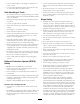
Troubleshooting Problem There are areas of uncut grass at the overlap between cutting units. There are full-width ridge lines in the cut across the direction of travel. Possible Cause Corrective Action 1. You are turning too tightly. 1. Increase the turning radius 2. The machine slides sideways when travelling across the face of a slope. 3. There is no ground contact on 1 end of the cutting unit because of poorly routed hoses or wrongly positioned hydraulic adapters. 4.
Problem There is scalping of the turf. There is excessive bedknife wear. The engine does not start with the ignition key. The battery has no power. The hydraulic fluid is overheating. Possible Cause 1. The undulations are too severe for the height of cut setting. 1. Use floating cutting units. 2. The height of cut is too low. 2. Raise the height of cut. 1. The bedknife is in heavy contact with the ground. 1. Raise the height of cut. 2. The cutting edges of the reel and/or bedknife are rounded. 3.
Problem Possible Cause Corrective Action 1. The parking brake is engaged. 1. Disengage the parking brake. 2. The fluid level is low. 3. The reservoir has the wrong kind of fluid. 4. The drive pedal linkage is damaged. 6. The transmission bypass valve is open. 7. There is a broken drive coupling. 2. Fill the reservoir to the correct level. 3. Drain the reservoir and fill it with the correct fluid. 4. Check the linkage and replace any damaged or worn parts. 5.
Problem A cutting unit fails to lift out of work. The cutting units do not follow the contours of the ground. The cutting units fail to start up when lowered into work. Possible Cause 1. There is a lift cylinder seal failure. 1. Replace the seals. 2. The pressure relief valve is jammed open or wrongly set. 3. There is a malfunctioning control valve. 4. There is mechanical blockage. 2. Have the relief valve pressure checked. Consult your authorized distributor. 3. Overhaul the control valve. 4.
Notes:
European Privacy Notice The Information Toro Collects Toro Warranty Company (Toro) respects your privacy. In order to process your warranty claim and contact you in the event of a product recall, we ask you to share certain personal information with us, either directly or through your local Toro company or dealer. The Toro warranty system is hosted on servers located within the United States where privacy law may not provide the same protection as applies in your country.
The Toro Warranty A Limited Warranty Conditions and Products Covered The Toro® Company and its affiliate, Toro Warranty Company, pursuant to an agreement between them, jointly warrant your Toro Commercial product (“Product”) to be free from defects in materials or workmanship for two years or 1500 operational hours*, whichever occurs first. This warranty is applicable to all products with the exception of Aerators (refer to separate warranty statements for these products).