Form No. 3395-718 Rev B CE Guard Kit Groundsmaster® 7200/7210 Traction Unit with 60in Side Discharge Mower Model No. 30658 Installation Instructions Safety Safety and Instructional Decals Safety decals and instructions are easily visible to the operator and are located near any area of potential danger. Replace any decal that is damaged or missing. decal119-6807 119–6807 1. Warning—no step © 2018—The Toro® Company 8111 Lyndale Avenue South Bloomington, MN 55420 Register at www.Toro.com.
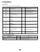
Installation Loose Parts Use the chart below to verify that all parts have been shipped. Procedure Description 1 2 3 4 5 6 7 8 9 Use Qty.
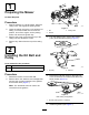
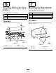
1 Preparing the Mower No Parts Required Procedure 1. Park the machine on a level surface, lower the cutting units, and engage the parking brake. 2. g026735 Figure 1 Lower the cutting unit to the 1 inch height-of-cut setting, move the throttle lever to the SLOW position, shut off the engine, set the parking brake, and remove the ignition key. 3. Remove the 2 belt covers from the top of the cutting unit and discard the covers. 4. Remove any debris from the top of the cutting unit. 1. Nut 3.
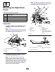
3 Mounting the Pulley Shield Parts needed for this procedure: 1 Pulley shield 1 Push nut Procedure 1. g029261 Remove the nuts and washers from the carriage bolts that secure the front of the gear box mounting brackets to the mower deck (Figure 4). Figure 5 1. Nut 2. Washer 3. Pulley shield g026735 Figure 4 1. Nut 3. Carriage bolt 2. Washer 2. Using the nuts removed in the previous step, mount the pulley shield to the gear box mounting brackets (Figure 5). 4 4. Retainer nut 5.
4 5 Mounting the Drive Shaft Cover Mounting the Left Deck Cover Not required on Groundsmaster Parts needed for this procedure: 360 Parts needed for this procedure: 1 Drive shaft cover 4 Lock washer (3/8 inch) 4 Hex-head screw (3/8 x 3/4 inch) 1 Grommet 1 Left deck cover 2 Grommet 1 Hex-flange screw (5/16 x 3/4 inch) 1 Push nut 2 Retainer nut Procedure Install the left deck cover (Figure 7). Procedure Note: The hole on the deck that the hex bolt uses will have to be opened up to 11.
7 Mounting the Center Deck Cover Mounting the Right Shield Parts needed for this procedure: Parts needed for this procedure: 1 Center deck cover 2 Hex flange screw (5/16 x 3/4 inch) 2 Push nut 1 Right shield 1 Right deck cover 2 Hex screw 2 Flange nut Procedure Procedure Mount the right shield onto the right deck cover as shown in Figure 9. Install the center deck cover (Figure 8). g029264 Figure 8 1. Nut 2. Center deck cover g029265 Figure 9 3. Knob 4. Retainer nut 6 1.
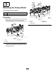
Note: You will have to drill a hole in the frame of the deck to install the lower bolt and retainer nut. Refer to Figure 13 and Figure 14. 8 Mounting the Right Deck Cover Parts needed for this procedure: 1 Hex screw (M8) 1 Hex flange screw (5/16 x 3/4 inch) 1 Flat washer (5/16 inch) 2 Push nut 1 Larger retainer nut Procedure g029267 1. For decks without grass collection system installed: Install the right shield assembly (Figure 10).
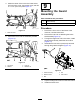
3. Mark the center of the hole in the lower tab at the front of the cover, remove the cover, and drill a 1.12 cm (0.44 inch) hole Figure 13. 9 Mounting the Guard Assembly Parts needed for this procedure: Guard assembly 1 Hex locknut Procedure g028773 Figure 13 1. Remove the front cover of the frame of the machine, near the brake lever. 2. Remove the bolt and nut attaching the brake shaft bracket (Figure 15). 3.
Notes:
Notes:
Declaration of Incorporation Model No. 30658 Serial No. None and Up Product Description Invoice Description CE Guard Kit CE KIT 60 SD DECK W/FRENCH GUARD General Description Directive Guard Kit 2006/42/EC, 2000/14/EC Relevant technical documentation has been compiled as required per Part B of Annex VII of 2006/42/EC. We will undertake to transmit, in response to requests by national authorities, relevant information on this partly completed machinery.