Form No. 3378-192 Rev A CE Light Kit Groundsmaster® 4000 Series Traction Unit with Yanmar Engine Model No. 30660 Installation Instructions WARNING CALIFORNIA Proposition 65 Warning This product contains a chemical or chemicals known to the State of California to cause cancer, birth defects, or reproductive harm. Installation Loose Parts Use the chart below to verify that all parts have been shipped.
Procedure Description 5 Headlamp bracket, R.H. (for models 30605 and 30609) Headlamp bracket, L.H. (for models 30605 and 30609) Rubber grommet (for models 30605 and 30609) Headlamp bracket (for model 30602, 30603, 30606 and 30607) Headlamp bracket, R.H. (for model 30604 and 30608) Headlamp bracket, L.H. (for model 30604 and 30608) Screw, 1/2 x 1 inch Locknut, 1/2 inch Headlamp R.H. Headlamp L.H. Wire harness, headlight Harness clip Use Qty.
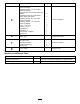
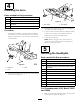
1 Disconnecting the Battery No Parts Required Procedure 1. Position the machine on a level surface, set the parking brake, lower the cutting units, turn the ignition off, and remove the key from the ignition switch. g021747 1 Figure 1 CAUTION 1. Steering tower cover If you leave the key in the ignition switch, someone could accidently start the engine and seriously injure you or bystanders. 2.
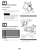
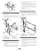
1 3 2 Installing the Turn Signal and Hazard Switches Parts needed for this procedure: 1 Switch, turn signal 1 Switch, hazard 1 Wire harness, platform Procedure g021714 1. From the under side the steering tower dash panel, press the plugs out of the holes shown in Figure 3. Figure 4 1. Hazard switch Note: On models 30602, 30603, 30606 and 30607 the turn signal and hazard switches are already installed on the machine. Skip to Step 4. 2. Turn signal switch 3.
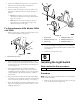
4 2 1 Installing the Horn Parts needed for this procedure: 1 Horn 1 Bolt (5/16 x 3/4 inch) 1 Flange nut (5/16 inch) 1 Horn switch 1 Horn button, rubber g021715 Figure 6 1. Horn switch 2. Horn button 3. Secure the horn switch to the tower by threading on the rubber horn button (Figure 6). Procedure 4. Locate the wire harness connectors inside the steering column tower. Plug the wire harness connectors labeled “horn” into the horn and switch. 1.
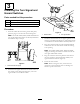
. Route the headlight wire harness underneath the front edge of the operator's platform. 7. Insert each harness connector through the end of the appropriate harness bracket, out the hole (grommet) and connect it to the headlight (Figure 8). 8. Secure the headlight wiring harness to the headlight brackets and operator's platform with the harness clips and cable ties. 9. Install the steering tower cover. g021734 Figure 7 For Groundsmaster 4010 and 4110, Models 30602, 30603 30606 and 30607 1.
5. Secure the headlight wiring harness to the operator's platform with the harness clips and cable ties. 1 2 6. Install the steering tower cover. 3 7. The front and rear cab lights cannot be used for CE applications. Disable the front and rear cab lights as follows: 4 • Front-Pop the lights out of the cab roof and disconnect the wires from the lights. Reinstall the lights into the cab. • Rear-Remove the screws securing the lenses to lights.
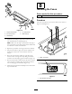
7 Installing the Rear Lamps Parts needed for this procedure: Figure 12 1. Plate 2. Right cover 3. Control arm 1 L.H. light mount 1 R.H. light mount 2 Rear lamp assembly 2 Jumper wire harness 2 Harness clip Procedure 2. Remove the (6) screws that secure the right cover to the right side of the control arm (Figure 12). 1. Remove the top bolt, washer and nut securing the rear bumper bracket to the left frame rail (Figure 14). Retain the bolt, washer and nut. Note: 3.
8 2 Installing the Fuses Parts needed for this procedure: 3 1 Fuse, 10 amp 5 Procedure Insert the 10 amp fuses into the fuse block slots shown in Figure 16 and Figure 17. 1 4 1 3 g021710 Figure 15 1. Jumper wire harness 4. L.H. lamp mount 2. R.H. lamp mount 5. Rear lamp (2) 3. Harness clip 3. Mount the rear lamp to lamp mount with bolts and nuts included with the lamp (Figure 15).
9 Connecting the Battery No Parts Required Procedure Connect the negative battery cable to the battery post.
Aiming the Headlights Operation Controls 1. Loosen the mounting nuts and position each headlight so that it points straight ahead. Light Switch 2. Tighten each mounting nut just enough to hold the headlight in position. Press the light switch (Figure 18) to the On position to activate the head lamps. 3. Place a flat piece of sheet metal over the face of the headlight. 4. Mount a magnetic protractor onto the plate. 5.