
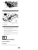
Installation Instructions


4.Plugtheconnectorbodyfromtheenclosedbeacon
wireharnessintothebeaconswitch.
5.Cabletietheharnessawayfromanyhotorrotating
componentsandavoidanypossiblepinchpoints.
Note:Whenroutingthewires,ensurethatthe
operationofthetiltsteeringdoesnotdamagethe
harnessorpullonthewires.
3
InstallingtheBeaconto
theROPS
(Whennotequippedwithacab)
Partsneededforthisprocedure:
1Beacon
1Beaconsocket
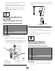
1
Beaconmount,ROPS
1U-bolt
2
Flangenut,3/8inch
1Wireharness,beacon
Procedure
1.Routethewireharnesstotherightuprightofthe
ROPS.
2.Looselysecurethebeaconmount(ROPS)totheside
oftheROPSpostwiththeU-boltand(2)3/8inch
angenuts,positioningasshowninFigure4.
5
1
4
3
2
G021938
Figure4
1.Beacon
4.Flangenut,3/8inch
2.Beaconsocket5.U-bolt
3.Beaconmount
3.Positionthebeaconmountsoitis37cm(14.50inches)
fromthetopoftheROPSandtightentheU-boltnuts
(Figure5).
G021939
Figure5
4.Mountthebeaconsockettothebeaconmountwith
thejamnutincluded(
Figure4).
5.Plugthebeaconontothesocketandtightenthewing
nut(Figure4).
6.RoutethewireharnessuptheROPSpostandplug
itintothebeaconsocket.
4
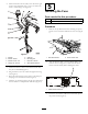
InstallingtheBeacon
(Whenequippedwithacab)
Partsneededforthisprocedure:
1Beacon
1Beaconsocket
1Beaconmount,cab
1
Flangenut,3/8inch
3
Cabletie
3Mountingpad
1
Bolt,3/8x7/8inch
1Wireharness,beacon
Procedure
1.Routethewireharnesstothefrontrightcornerpost
ofthecab.
3