
Installation Instructions
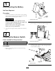
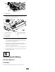


2.Securethebeaconmount(cab)tothetabontheright
cornerofthecabframewitha3/8x7/8inchscrew
anda3/8inchangenut(Figure6).
1
2
4
8
3
5
6
7
G021936
Figure6
1.Beacon
5.Cabletie
2.Beaconsocket6.Mountingpad
3.Beaconmount,cab
7.Bolt,3/8x7/8inch
4.Flangenut,3/8inch
8.Wireharness,beacon
3.Mountthebeaconsockettothebeaconmountwith
thejamnutincluded(Figure6).
4.Plugthebeaconontothesocketandtightenthewing
nut(Figure6).
5.Routethewireharnessupthecornerofthecabpost
andplugitintothebeaconsocket(Figure6).
6.Afxthe(3)mountingpadstothecabpostandsecure
thewireharnesstothepadswithcableties(Figure6).
5
InstallingtheFuse
Partsneededforthisprocedure:
1
Decal,fuse
1Fuse,10amp
Procedure
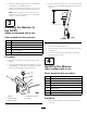
1.Removethe(2)Allenheadscrewssecuringthepower
centercovertotheframeandremovethecover(Figure
7).
Figure7
1.Allenheadscrews2.Powercentercover
2.Afxthebeacondecaltothefuseblockdecalatthe
locationshownin(Figure8).Makesurethedecal
surfaceiscleananddrybeforeafxingthedecal.
1
G021956
Figure8
1.Installbeacondecalhere
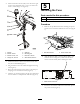
3.Routethewireharnessunderthetractionunitupinto
thepowercenter(Figure9).
4