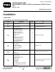
Form No. 3437-339 Rev A Homologation Kit Groundsmaster® 4500-D, 4700-D or Reelmaster® 7000-D Traction Unit Model No. 30667 Installation Instructions Installation Loose Parts Use the chart below to verify that all parts have been shipped. Procedure 1 2 3 4 5 6 © 2019—The Toro® Company 8111 Lyndale Avenue South Bloomington, MN 55420 Description Use Qty. No parts required – Disconnect the battery. No parts required – Drill the mounting holes.
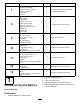
Procedure 7 8 9 10 11 12 13 Description 1 1 2 2 1 1 1 1 1 2 1 2 2 4 1 2 1 1 4 4 2 2 1 1 2 2 2 1 1 3 3 11 Steering-column bracket Column mount bracket Carriage bolt (3/8 x 3/4 inch) Flange nut (3/8 inch) Foam strip Cable tie Carriage bolt (#10 x 5/8 inch) Locknut (#10) Sensor plate Flange nut (1/4 inch) Brake-sensor bracket Bolts (1/4 x 3/4 inch) Slotted screw (#6 x 1 inch) Washer (#6) Brake sensor Locknut (#6) Left light bracket Right light bracket Screw (5/8 x 3 inches) Flat washer Jam nut (5/8 inc
2 Drilling the Mounting Holes No Parts Required Drilling the Holes for the Headlights and the Wire Harness 1. 2. 3. g034758 Remove the nuts from the 2 carriage bolts securing the headlights to the traction-unit frame (Figure 1). Figure 1 Remove the 2 self-tapping bolts securing the top of the platform shroud to the frame (Figure 1). 1. Platform shroud 4. Self-tapping bolt (2) 2. Headlight assembly (halogen shown) 5. Headlight connector 3. Carriage bolt (2) 6.
Drilling the Holes for the Horn Bracket Using the dimensions in Figure 3, locate and drill 2 holes (7 mm) through both walls of the roller-support tube. g029796 Figure 3 1. 1.9 cm (3/4 inch) 3. 25.4 cm (10 inches) 2. 3.8 cm (1-1/2 inches) 4. 7 mm (9/32 inch) diameter g029663 Figure 4 Drilling the Holes in the Front Footrest for the Brake-Pedal Switch 1. 15.5 cm (6-7/64 inches) 4. 17 mm (11/16 inch) 2. 32 mm (1-1/4 inches) 5. 7 mm (9/32 inch) diameter 3.
Drilling the Mounting Holes in the Rear Bumper for the License Plate 3 Using the dimensions shown in Figure 5, locate and drill 2 holes (9/32 inch) through the outside wall of the rear bumper. Installing the Headlights Parts needed for this procedure: 1. 8.3 cm (3-1/3 inches) 3. 52.07 cm (20-1/2 inches) 4. Drill a hole (9/32 inch) here.
Installing the Headlight Bracket to a Cab Model Note: Ensure that the turn-signal lens on the headlight is positioned toward the outside of the traction unit. 1. Install a bent-plate bracket onto each of the upper corners of the lower front panel of the cab with the existing screws as shown in Figure 8. g029778 Figure 7 Right headlight assembly shown 1. Right headlight bracket 4. Headlight arm 2. Articulated-joint shell 5. Locknut (10 mm) 3. Articulated joint 3.
4 Installing the Horn Parts needed for this procedure: 1 Horn 1 Horn bracket 1 Bolt (3/8 x 5/8 inch) 1 Flange nut (3/8 inch) 2 Bolt (1/4 x 2 inches) 2 Nut (1/4 inch) Procedure 1. g034338 Secure the horn strap to the horn bracket with a bolt (3/8 x 5/8 inch) and a flange nut (3/8 inch) as shown in Figure 10. Figure 9 1. Nut (5/16 inch) 4. Headlight bracket 2. Washer 3. Spacer 5. Bracket tab 6. Bolt (5/16 x 1-5/8 inch) 4.
5 6 Installing the Relay Switch Installing the Flasher Module and Switches on the Column Bracket Parts needed for this procedure: 1 Relay switch 1 Serrated hex-head flange bolt (#8 x 1/2 inch) 1 Locknut (#8) Parts needed for this procedure: Procedure Secure the relay switch under the battery cover with a serrated hex-head flange bolt (#8 x 1/2 inch) and a locknut (#8) at the location shown in Figure 11. Note: Do not overtighten the bolt.
7 Installing the Column-Bracket Assembly onto the Steering Column Parts needed for this procedure: g034342 1 Steering-column bracket 1 Column mount bracket 2 Carriage bolt (3/8 x 3/4 inch) 2 Flange nut (3/8 inch) 1 Foam strip 1 Cable tie Figure 12 1. On-Off-On rocker switch 2. Horn button 3. Locknut 4. Paddle switch 5. Beacon switch 2. 6. Column bracket 7. Speed nut (2) Procedure 1. 8. Flasher module 9. Horn switch 10.
2. Insert the cable tie through the slots in the column mount bracket so that the ends are outward, but do not tie them. 1. 3. Install the steering-column bracket onto the steering column with the mounting bracket, 2 carriage bolts, and 2 flange nuts (Figure 14). Disassemble the proximity-sensor assembly on the brake-pedal lever (Figure 16) and set aside all the parts except the proximity sensor. Important: Ensure that the top of the steering-column bracket is 21 mm (0.
Important: After you complete the installation of the light kit, verify that the brake sensor activates the brake lights when the brake pedal is pressed. Realign the brake sensor if necessary. 9 Installing the Rear Lamps Parts needed for this procedure: 1 Left light bracket 1 Right light bracket 4 Screw (5/8 x 3 inches) 4 Flat washer 2 Jam nut (5/8 inch) 2 Rear-lamp assembly Procedure 1. g029762 Note: Stabilize the reservoir and bracket to Figure 17 prevent them from falling. 5.
Note: The left and right light brackets are different. Ensure that you use the correct mount. 10 Installing the License-Plate Bracket Parts needed for this procedure: 1 Plate light 1 Plate bracket 2 Screw (#10 x 5/8 inch) 2 Locknut (#10) 2 Self-tapping screw (5/16 x 1/2 inch) Procedure g023194 1. Figure 19 1. Left light bracket 3. Rear lamp 2. Right light bracket Secure the plate light to the license-plate bracket with 2 screws (#10 x 5/8 inch) and 2 locknuts (Figure 21).
11 Installing the Wire Harness Parts needed for this procedure: 1 Wire harness 1 Switch-panel-enclosure cover 3 Screw (#10 x 1/2 inch) 3 Mounting pad 11 Cable tie 2 Jumper wire harness (LED headlights only) Procedure g023198 Figure 23 Use the following instructions and illustrations to route and connect the wire harness. 1. Compartment clamp 2. 2.
g023200 Figure 25 1. Self-tapping screws (#8 x 1/2 inch) 3. Junction block 2. Ground-block terminal 4. Wire harness fuse block 5. Connect the large-ring terminal, from the wire harness, to the stud on the junction block (Figure 25). 6. Install the compartment clamp and seal to the traction unit with the flange-head screw (Figure 23). 7. Route the front end of the wire harness under the operator platform to the front of the traction unit (Figure 26). g311790 Figure 26 1.
g312684 Figure 28 1. Turn signal connector 3. Hazard connector 2. Horn connector 4. Beacon connector 16. g312120 Figure 27 1. Platform shroud 5. Headlight wire connectors 2. Halogen headlight 6. Hole for wire harness 3. Carriage bolt and nut 7. LED headlight Install the cover onto the column-bracket assembly with 2 hex socket button-head screws as shown in Figure 29. 4. Washer-head screws and nuts 13.
12 Installing the Fuses and Decal Parts needed for this procedure: g034579 Figure 30 19. Plug the wire-harness connector into the light connector. 20. Route the left, rear wire harness under the left side of the traction unit to the left, rear light (Figure 30). 3 Fuse (10 A) 1 Fuse (15 A) 1 Fuse-box decal Procedure 1. Insert the 3 (10 A) and 1 (15 A) fuses into the fuse block slot (Figure 32). g029811 Figure 32 1. Fuse (10 A) 3. Fuse (10 A) 2. Fuse (10 A) 4.
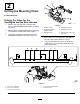
g032309 Figure 34 Right side shown 1. Plate 2. Light-kit bracket 2. 3. Holes Secure the plates to the light-kit brackets with the 4 hex-head screws (1/4 x 2-1/2 inches) and 4 locknuts (1/4 inch) as shown in Figure 35. g034580 Figure 33 1. 6 mm (1/4 inch) 2. Fuse-box decal 13 Installing the Decal-Mounting Plates Parts needed for this procedure: 2 Plate 4 Decal 4 Hex-head screw (1/4 x 2-1/2 inches) 4 Locknut (1/4 inch) g032310 Figure 35 Right side shown 3. Light-kit bracket 2.
Operation Controls Hazard Switch Press the hazard switch (Figure 37) to the ON position to activate the front and rear flashing hazard lights. g032311 Figure 36 Right side shown 1. Plate 2. Decals 14 Connecting the Battery No Parts Required g034583 Figure 37 Procedure 1. Turn signal switch 3. Hazard switch 2. Horn button 4. Beacon switch (optional) Connect the battery; refer to your machine Operator’s Manual.
Aiming the Headlights 1. Loosen the mounting nuts and position each headlight so that it points straight ahead. 2. Tighten each mounting nut just enough to hold the headlight in position. 3. Place a flat piece of sheet metal over the face of the headlight. 4. Mount a magnetic protractor onto the plate. 5. While holding the assembly in place, carefully tilt the headlight downward 3 degrees, then tighten the nut. 6. Repeat the procedure for the other headlight.