
Operator's Manual


g032630
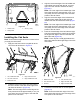
Figure82
1.Throughhole4.Returnhose
2.Supplyhose5.Controlvalve
3.Tube
6.Connectthereturnhosetothecontrolvalve
(Figure82).
7.Tightenallhosettings.
Note:Donotsecurethehosestohotormovingparts.
InstallingtheWheels
1.Installthewheelontothehub(Figure83).
g032628
Figure83
1.Hub3.Lugnut
2.Wheel
2.Usethelugnutstosecurethewheelstothe
frame(Figure83).
3.Torquethelugnutstothe88to115N∙m(65to
85ft-lb)inthefollowingorder(Figure84).
g032629
Figure84
InstallingtheTracks
CAUTION
Thetrackguideshavemanypinchpoints.
Comingintocontactwithoneofthesepinch
pointscouldcauseseverepersonalinjury.
Carefullygrasptherubbertrackontheouter
edgesoutboardofthesteelguideswhen
movingthetrack.
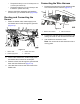
1.Place2jackstandsunderneaththerearofframe
tosupportthemachinewhenyouliftthefrontof
themachine(Figure85)
g032669
Figure85
1.Machineframe
2.Jackstand
2.Removethelocknutandwasherfromthe
threadedstudonthebogie-stopassemblyand
setthemaside(Figure86).
38