
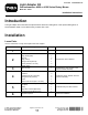
Installation Instructions
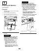


Ensurethattheswitchsnapssecurelyintothe
bracket.
g204950
Figure9
1.Light
3.Columnbracket
2.Rockerswitch(partofthe
optionalEUlightkitor
optionalNorthAmerican
roadlightkit)
4.Shortange(column
bracket)
3
ConnectingtheWire
HarnesstotheColumn
BracketAssembly
Partsneededforthisprocedure:
1Wireharness
Procedure
•IfyourmachinehastheoptionalNorthAmerican
roadlightkitandtheoptionalhornkitisnot
installed,connectthewireharnessasfollows:
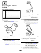
1.Plugthe8-socketconnectorlabeledHAZARD
SWITCH-NAontothe8-pinconnectorofthe
hazardswitch(Figure10).
g247147
Figure10
1.8-pinconnector(hazard
switch)
4.8-pinconnector(paddle
switch)
2.8-socketconnector
(HAZARDSWITCH-NA)
5.Hornterminals
3.8-socketconnector(TURN
SIGNAL-NA)
2.Plugthe8-socketconnectorlabeledTURN
SIGNAL-NAontothe8-pinconnectorofthe
paddleswitch(Figure10).
•IfyourmachinehastheoptionalEUlightkit,
connectthewireharnessasfollows:
1.Plugthe8-socketconnectorlabeledHAZARD
SWITCH-CEontothe8-pinconnectorofthe
hazardswitch(Figure11).
5