Form No. 3444-316 Rev B Groundsmaster® 7210 Series Traction Unit Model No. 30695—Serial No. 408000000 and Up Register at www.Toro.com.
injury and product damage. You are responsible for operating the product properly and safely. This product complies with all relevant European directives; for details please see the separate product specific Declaration of Conformity (DOC) sheet. Visit www.Toro.com for product safety and operation training materials, accessory information, help finding a dealer, or to register your product.
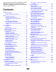
Servicing the Cutting-Unit Gearbox Lubricant ....................................................... 49 Engine Maintenance ........................................... 50 Engine Safety ................................................... 50 Checking the Air Cleaner .................................. 50 Servicing the Air Cleaner .................................. 51 Servicing the Engine Oil.................................... 51 Servicing the Diesel-Oxidation Catalyst (DOC) and the Soot Filter ................
Safety • Do not operate the machine without all guards and other safety protective devices in place and functioning properly on the machine. This machine has been designed in accordance with ANSI B71.4-2017 and with EN ISO 5395 when you complete the setup procedures and install the CE kit, per the Declaration of Conformity. • Keep your hands and feet away from rotating parts. Keep clear of the discharge opening. • Keep bystanders and children out of the operating area.
decal107-1866 107-1866 Note: This machine complies with the industry standard stability test in the static lateral and longitudinal tests with the maximum recommended slope indicated on the decal. Review the instructions for operating the machine on slopes in the Operator’s Manual as well as the conditions in which you would operate the machine to determine whether you can operate the machine in the conditions on that day and at that site.
decal117-3276 117-3276 decal110-9796 110-9796 1. Engine coolant under pressure 3. Warning—do not touch the hot surface. 2. Explosion hazard—read the Operator's Manual. 4. Warning—read the Operator's Manual. 1. Read the Operator's Manual for information on fuses. decal133-8062 133-8062 decal106-9290 106-9290 1. Inputs 5. In seat 2. Not active 6. Power takeoff (PTO) 9. Outputs 10. Power takeoff (PTO) 3. High temperature shutdown 7. Parking brake off 11. Start 4.
decal120-9195 120-9195 Note: This machine complies with the industry standard stability test in the static lateral and longitudinal tests with the maximum recommended slope indicated on the decal. Review the instructions for operating the machine on slopes in the Operator’s Manual as well as the conditions in which you would operate the machine to determine whether you can operate the machine in the conditions on that day and at that site.
decal121-3363 121–3363 1. Fast 3. Engage PTO 2. Slow 4. Disengage PTO decal125-2747 125–2747 1. Read the Operator’s Manual for maintenance information.
decal127-6519 127-6519 1. Transport position 2.
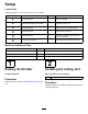
Setup Loose Parts Use the chart below to verify that all parts have been shipped. Procedure Description 1 2 3 4 5 6 Use Qty. No parts required – Raise the ROPS. Cutting unit Installation Instructions 1 Install the cutting unit. No parts required – Adjust the left, front caster wheel. No parts required – Check the tire pressure. No parts required – Check the hydraulic fluid, engine oil, and coolant levels. Production-year decal 1 Install the decal (CE machines only).
3 5 Adjusting the Left, Front Caster Wheel Checking the Fluid Levels No Parts Required No Parts Required Procedure Procedure 1. Adjust the left, front caster wheel to the outside position for 183 cm (72 inch) cutting units and to the inside position for 152 cm and 158 cm (60 inch and 62 inch) cutting units (Figure 3). Check the hydraulic-fluid level before starting the engine, refer to Checking the Hydraulic System (page 66). 2.
Controls Product Overview Note: Determine the left and right sides of the machine from the normal operating position. Become familiar with all the controls before you start the engine and operate the machine (Figure 5 and Figure 6). Motion-Control Levers The motion-control levers control the forward and rearward motions as well as the turning of the machine. Refer to Driving the Machine (page 27).
Power-Takeoff (PTO) Switch The power-takeoff (PTO) switch starts and stops the mower blades. InfoCenter LCD Display The InfoCenter LCD display (Figure 6) shows information about your machine, such as the operating status, various diagnostics, and other information about the machine. The screens that display depend on which buttons you select. The purpose of each button may change depending on what is required at the time.
Specifications g242498 Figure 8 Description Figure 8 reference Dimension or Weight Height with roll bar up C 183 cm (72 inches) Height with roll bar down D 125 cm (49 inches) Overall length F 253 cm (99-1/2 inches) Overall width B 145 cm (57 inches) Wheel base E 145 cm (57-1/4 inches) Wheel tread (tire center to center) rear A 114 cm (45 inches) 14
Ground clearance 10 cm (4 inches) Weight, with 72-inch Side-Discharge Cutting unit (30354 or 30481) 1052 kg (2,320 lb) Weight, with 60-inch Side-Discharge Cutting unit (30456) 1036 kg (2,284 lb) Weight, with 72-inch Base Cutting unit (30353) 1012 kg (2,231 lb) Weight, with 62-inch Base Cutting unit (30457) 990 kg (2,183 lb) Weight with the 100-inch Rear-Discharge Cutting unit (31101) 1200 kg (2,646 lb) Note: Specifications and design are subject to change without notice.
Fuel Safety Operation • Use extreme care in handling fuel. It is flammable and its vapors are explosive. Note: Determine the left and right sides of the machine from the normal operating position. • Extinguish all cigarettes, cigars, pipes, and other sources of ignition. Before Operation • Use only an approved fuel container. • Do not remove the fuel cap or fill the fuel tank while the engine is running or hot. Before Operation Safety • Do not add or drain fuel in an enclosed space.
Filling the Fuel Tank Fuel Table Diesel fuel specification Location Important: The fuel tanks are connected, but the fuel does not transfer quickly from one tank to the other. It is important when filling that you park on a level surface. If you park on a hill, you may inadvertently overfill the tanks. ASTM D975 No. 1-D S15 USA No. 2-D S15 EN 590 European Union ISO 8217 DMX International JIS K2204 Grade No. 2 Japan KSM-2610 Korea Important: Do not overfill the fuel tanks.
Adjusting the Roll Bar WARNING To avoid injury or death from rollover, keep the roll bar in the raised locked position and use the seat belt. g031636 Ensure that the seat is secured with the seat latch. WARNING There is no rollover protection when the roll bar is in the down position. • Do not operate the machine on uneven ground or on a hill side with the roll bar in the down position. • Lower the roll bar only when absolutely necessary.
Raising the Roll Bar Adjusting the Height of Cut Raise the roll bar as shown in Figure 10. You can adjust the height of cut from 2.5 to 15.8 cm (1 to 6 inches) in 6 mm (1/4 inch) increments by relocating the stop pin into different hole locations. 1. With the engine running, push the deck-lift switch up until the cutting unit is fully raised and release the switch immediately (Figure 26). 2.
Using the Safety-Interlock System position. Start the engine. While the engine is running, release the parking brake, engage the PTO, and rise slightly from the seat; the engine should shut off within 2 seconds. CAUTION If the safety-interlock switches are disconnected or damaged, the machine could operate unexpectedly, causing personal injury. • Do not tamper with the interlock switches. • Check the operation of the interlock switches daily and replace any damaged switches before operating the machine.
Changing the Seat Suspension details on using the rest of the SCM functions, refer to the Service Manual, available through your authorized Toro distributor. The seat is adjustable to provide a smooth and comfortable ride. Position the seat where you are most comfortable. To adjust it, turn the knob in front either direction to provide the best comfort (Figure 16). g004927 Figure 14 1. High temperature shutdown—the engine temperature has exceeded safe levels and the engine has been shut down.
Using the InfoCenter Control InfoCenter Icon Description The InfoCenter LCD display shows information about your machine, such as the operating status, various diagnostics and other information about the machine (Figure 18). There is a splash screen and main information screen of the InfoCenter. You can switch between the splash screen and main information screen at any time by pressing any of the InfoCenter buttons and then selecting the appropriate directional arrow.
Using the Menus InfoCenter Icon Description (cont'd.) To access the InfoCenter menu system, press the menu access button while at the main screen. This brings you to the main menu. Refer to the following tables for a synopsis of the options available from the menus: Operator must release switch Operator should change to indicated state Main Menu Symbols are often combined to form sentences.
Titles are in the selected language, but menu items are in English. About Menu Item Description Model Lists the model number of the machine. SN Lists the serial number of the machine. Machine Controller Revision Lists the software revision of the master controller. InfoCenter Revision Lists the software revision of the InfoCenter. CAN Bus Lists the machine communication bus status.
During Operation • Never leave a running machine unattended. • Before you leave the operator’s position, do the During Operation Safety General Safety • The owner/operator can prevent and is responsible for accidents that may cause personal injury or property damage. • Wear appropriate clothing, including eye • protection; long pants; substantial, slip-resistant footwear; and hearing protection. Tie back long hair and do not wear loose clothing or loose jewelry.
Slope Safety Operating the Parking Brake • Slopes are a major factor related to loss of control and rollover accidents, which can result in severe injury or death. You are responsible for safe slope operation. Operating the machine on any slope requires extra caution. Always engage the parking brake when you stop the machine or leave it unattended. • Evaluate the site conditions to determine if the Engaging the Parking Brake slope is safe for machine operation, including surveying the site.
Starting the Engine Driving the Machine Note: The glow plug light illuminates for 6 seconds when you turn the ignition key to the RUN position. Turn the ignition to the START position after the light goes out. The throttle control regulates the engine speed as measured in rpm (revolutions per minute). Place the throttle control in the FAST position for best performance. Always operate in the FAST throttle position when running powered attachments.
g243800 Figure 25 Operating the Mower Using the Deck-Lift Switch g004532 Figure 24 1. Motion-control lever—NEUTRAL-LOCK position 4. Backward 2. Center, unlocked position 5. Front of the machine The deck-lift switch raises and lowers the cutting unit (Figure 26). The engine must be running for you to use this lever. 3. Forward Shutting Off the Engine CAUTION Children or bystanders may be injured if they attempt to move or operate the tractor while it is unattended.
g243799 Figure 27 Disengaging the PTO g009174 Figure 28 g020873 Figure 26 1. Deck-lift switch • To lower the cutting unit, push the deck-lift switch down (Figure 26). Important: When you lower the cutting unit, it sets in a float/idle position. • To raise the mover deck, push the deck-lift switch up (Figure 26). Important: Do not continue to hold the switch up or down after the mower has fully raised or lowered. Doing so damages the hydraulic system.
Cutting Grass with the Machine Operate and maintain your machine with the function of the DPF in mind. Engine load at high idle (full throttle) engine speed generally produces adequate exhaust temperature for DPF regeneration. Note: Cutting grass at a rate that loads the engine Important: Minimize the amount of time that you promotes DPF regeneration. 1. Move the machine to the job site. 2. Whenever possible, set the throttle to high idle. 3. Engage the PTO switch. 4.
Engine Warning Messages—Soot Accumulation Indication Level Level 1: Engine Warning Fault Code g213866 Engine Power Rating Recommended Action The computer de-rates the engine power to 85%. Perform a parked regeneration as soon as possible; refer to Parked or Recovery Regeneration (page 38). The computer de-rates the engine power to 50%. Perform a recovery regeneration as soon as possible; refer to Parked or Recovery Regeneration (page 38).
DPF Ash Accumulation • When enough ash accumulates, the engine • The lighter ash is discharged through the exhaust system; the heavier ash collects in the soot filter. • Ash is a residue of the regeneration process. Over • time, the diesel particulate filter accumulates ash that does not discharge with the engine exhaust. • • The computer for the engine calculates the amount of ash accumulated in the DPF.
Types of Diesel Particulate Filter Regeneration Types of diesel particulate filter regeneration that are performed while the machine is operating: Type of Regeneration Conditions that cause DPF regeneration DPF description of operation Passive Occurs during normal operation of the machine at high-engine speed or high-engine load • The InfoCenter does not display an icon indicating passive regeneration.
Types of diesel particulate filter regeneration that require you to park the machine: (cont'd.) Type of Regeneration Conditions that cause DPF regeneration DPF description of operation Recovery Occurs because the operator ignored requests for a parked regeneration and continued operating the machine, adding more soot to the DPF • When the reset-standby/parked or recovery regeneration icon or ADVISORY #190 displays in the InfoCenter, a recovery regeneration is requested.
press the right button to select the Technician entry (Figure 35). DPF Operation Table (cont'd.) State Description Reset Regen The engine computer is running a reset regeneration. Parked Stby The engine computer is requesting that you run a parked regeneration. Parked Regen You initiated a parked regeneration request and the engine computer is processing the regeneration. Recov. Stby The engine computer is requesting that you run a recovery regeneration. Recov.
Assist DPF Regeneration • The icon displays in the InfoCenter while the reset regeneration is processing. • The engine computer adjusts engine settings to • Whenever possible, do not shut off the engine or raise the exhaust temperature. reduce engine speed while the reset regeneration is processing. • While operating the machine, run the engine at full engine speed and high load when possible to promote DPF regeneration.
g227304 g224394 Figure 40 2. Figure 42 Press the right button to change the inhibit regeneration setting from On to Off (Figure 40) or from Off to On (Figure 41). Note: If the InfoCenter displays ADVISORY #186 (Figure 43), set the engine to full throttle (high idle) to allow the reset regeneration to continue.
Parked or Recovery Regeneration regeneration required—power takeoff disabled ADVISORY #189 (Figure 47). • When the engine computer requests either a parked regeneration or a recovery regeneration, the regeneration request icon (Figure 44) displays in the InfoCenter. g224398 Figure 47 Important: Perform a parked regeneration to restore the PTO function; refer to Preparing to Perform a Parked or Recovery Regeneration (page 39) and Performing a Parked or Recovery Regeneration (page 39).
Preparing to Perform a Parked or Recovery Regeneration 1. Ensure that the machine has fuel in the tank for the type of regeneration you are performing: • Parked Regeneration: Ensure that you g243798 Figure 51 have 1/4 tank of fuel before performing the parked regeneration. • Recovery Regeneration: Ensure that you Important: Perform a recovery regeneration have 1/2 tank of fuel before performing the recovery regeneration.
3. At the DPF checklist screen, verify that the parking brake is engaged and that the engine speed is set to low idle (Figure 56). g224402 g224407 g224629 Figure 54 2. At the VERIFY FUEL LEVEL screen, verify that you have 1/4 tank of fuel if you are performing the parked regeneration or 1/2 tank of fuel if you are performing the recovery regeneration, and press the right button to continue (Figure 55). g227679 Figure 56 4.
5. The InfoCenter displays the INITIATING DPF REGEN message (Figure 58). Check Message and Corrective Action Table (cont'd.) g224411 Corrective Action: Troubleshoot the engine fault and retry DPF regeneration. g227681 Figure 58 6. The InfoCenter displays the time to complete message (Figure 59). Corrective Action: Start and run the engine. Corrective Action: Run the engine to warm the coolant temperature to 60°C (140°F). g224406 g224406 Corrective Action: Change the engine speed to low idle.
Note: While the DPF regeneration Canceling a Parked or Recovery Regeneration runs, the InfoCenter displays the high exhaust-temperature icon 9. Use the Parked Regen Cancel or Recovery Regen Cancel setting to cancel a running parked or recovery regeneration process. . 1. When the engine computer completes a parked or recovery regeneration, the InfoCenter displays ADVISORY #183 (Figure 61). Press the left button to exit to the home screen. Access the DPF Regeneration menu (Figure 63).
Operating Tips inside the mower, cutting quality eventually becomes unsatisfactory. Fast Throttle Setting/Ground Speed To reduce the risk of fire hazard, keep the engine, muffler, battery compartment, parking brake, cutting units, and fuel storage compartment free of grass, leaves, or excessive grease. Clean up any spilled oil or fuel. To maintain enough power for the machine and deck while mowing, operate the engine at the FAST throttle position and adjust your ground speed for conditions.
Hauling the Machine Important: Always push the machine by hand and never a long distance. Never tow the machine, because damage to the hydraulic system may occur. Use a heavy-duty trailer or truck to haul the machine. Ensure that the trailer or truck has all the necessary brakes, lighting, and marking as required by law. Please carefully read all the safety instructions. Knowing this information could help you, your family, pets, or bystanders avoid injury.
Loading the Machine Use extreme caution when loading or unloading machines onto a trailer or a truck. Use a full-width ramp that is wider than the machine for this procedure. Drive the machine up ramps in reverse and drive it down ramps in a forward direction (Figure 67). g027995 Figure 67 1. Drive the machine up the ramp in reverse. 2. Drive the machine forward down the ramp. Important: Do not use narrow individual ramps for each side of the machine.
Maintenance • Note: Determine the left and right sides of the machine from the normal operating position. • Important: Refer to your engine owner’s manual for additional maintenance procedures. • Note: Download a free copy of the electrical or hydraulic schematic by visiting www.Toro.com and searching for your machine from the Manuals link on the home page. • • Maintenance Safety • • Before you leave the operator’s position, do the • following: – Park the machine on a level surface.
Maintenance Service Interval Maintenance Procedure Every 400 hours • Change the cutting-unit gearbox lubricant. • Service the air-cleaner filter. —service the filter also when the air-cleaner indicator shows red; service the air-cleaner filter more frequently in extremely dusty or dirty conditions. • Service the air cleaner. • Replace the engine fuel filter. • Replace the fuel-filter canister for the water separator. • Drain water or other contaminants from the water separator.
Daily Maintenance Checklist Duplicate this page for routine use. Maintenance Check Item For the week of: Mon. Tues. Wed. Thurs. Fri. Check the safety-interlock operation. Check the grass deflector in the down position (if applicable). Check the parking-brake operation. Check the fuel level. Check the hydraulic fluid level. Check the engine-oil level. Check the cooling-system fluid level. Check the drain water/fuel separator. Check the air-filter restriction indicator.
CAUTION If you leave the key in the ignition switch, someone could accidently start the engine and seriously injure you or other bystanders. Remove the key from the ignition before you do any maintenance. Lubrication 4. Greasing the Bearings and Bushings Move the throttle lever to the SLOW position, shut off the engine, remove the key, and wait for all moving parts to stop before leaving the operating position. 5. Lift the footrest, exposing the top of the cutting unit. 6.
Changing the Cutting-Unit Gearbox Lubricant Engine Maintenance Service Interval: After the first 50 hours Engine Safety Every 400 hours 1. Position the machine and cutting unit on a level surface. 2. Lower the cutting unit to the 2.5 cm (1 inch) height of cut. 3. Disengage the PTO, move the motion-control levers to the NEUTRAL-LOCK position, and engage the parking brake. 4.
Servicing the Air Cleaner Servicing the Engine Oil Service Interval: Every 400 hours Oil Specification Note: If the foam gasket in the cover is damaged, replace it. Use high-quality, low-ash engine oil that meets or exceeds the following specifications: Important: Avoid using high-pressure air, which could force dirt through the filter into the intake tract.
g020435 Figure 72 1. Dipstick g021890 Figure 73 2. Oil-fill cap 1. Oil-drain plug 4. If the oil is below the safe range, remove the fill cap (Figure 72) and add oil until the level reaches the Full mark. Important: Do not overfill the engine with oil. Note: When using different oil, drain all old oil from the crankcase before adding new oil. 5. Install the oil-fill cap and dipstick. 6. Close the hood and secure it with the latches. Crankcase Oil Capacity 5.2 liters (5.5 qt) with the filter.
Servicing the Diesel-Oxidation Catalyst (DOC) and the Soot Filter Fuel System Maintenance Note: Refer to Fuel Specification (page 16) for proper fuel recommendations. Service Interval: Every 3,000 hours or clean the soot filter if engine faults SPN 3720 FMI 16 or SPN 3720 FMI 0 display in the InfoCenter. DANGER Under certain conditions, diesel fuel and fuel vapors are highly flammable and explosive. A fire or explosion from fuel can burn you and others and can cause property damage.
4. 5. included with the machine, for additional information. Install the dry filter canister, by hand, until the gasket contacts the filter head, then rotate it an additional 1/2 turn. Start the engine and check for fuel leaks around the filter head. Before storage—Drain and clean the fuel tank. In addition to the listed service interval, drain and clean the tank if the fuel system becomes contaminated or if you are storing the machine for an extended period. Use clean fuel to flush out the tank.
Electrical System Maintenance WARNING Incorrect battery cable routing could damage the machine and cables causing sparks. Sparks can cause the battery gasses to explode, resulting in personal injury. Electrical System Safety • Always disconnect the negative (black) battery cable before disconnecting the positive (red) cable. • Disconnect the battery before repairing the machine. Disconnect the negative terminal first and the positive last. Connect the positive terminal first and the negative last.
Drive System Maintenance Checking the Tire Pressure Service Interval: Every 50 hours/Monthly (whichever comes first) Maintain the air pressure in the front and rear tires (Figure 79). The correct air pressure is 124 kPa (15 psi) in the rear tires and 103 kPa (25 psi) in the caster wheels. Uneven tire pressure can cause an uneven cut. Note: Check the tires when they are cold to get the most accurate pressure reading. g022100 Figure 77 1. Side panel cover 2.
Replacing the Caster Wheels and Bearings 1. 2. Cooling System Maintenance Obtain a new caster-wheel assembly, cone bearings, and bearing seals from your Authorized Toro Distributor. Cooling System Safety Remove the locknut from the bolt (Figure 80). • Swallowing engine coolant can cause poisoning; keep out of reach from children and pets. • Discharge of hot, pressurized coolant or touching a hot radiator and surrounding parts can cause severe burns.
Coolant Specification Note: The coolant level should be between the marks on the side of the tank. The coolant reservoir is filled at the factory with a 50/50 solution of water and ethylene glycol base extended-life coolant. Important: Use only commercially available coolants that meet the specifications listed in the Extended Life Coolant Standards Table. Do not use conventional (green) inorganic-acid technology (IAT) coolant in your machine. Do not mix conventional coolant with extended-life coolant.
Brake Maintenance Cleaning the Radiator Service Interval: Before each use or daily Adjusting the Parking-Brake Interlock Switch Every 1,500 hours—Replace moving hoses. Every 200 hours—Inspect the cooling-system hoses and seals. Replace them if cracked or torn. Every 2 years—Flush and replace the cooling-system fluid. Clean the radiator to prevent the engine from overheating. 1.
4. Belt Maintenance Move the switch up or down on the bracket until the distance between the brake-shaft sensor and the switch plunger is 4 mm (5/32 inch) as shown in Figure 83. does not contact the switch plunger. Checking the Alternator-Belt Tension 5. Secure the switch jam nuts. Service Interval: Every 100 hours 6. Test the adjustment as follows: Note: Make sure that the brake-shaft sensor A. B.
Controls System Maintenance Adjusting the Control-Lever Neutral-Interlock Switch 1. Stop the machine, move the motion-control levers to the NEUTRAL-LOCK position, engage the parking brake, and remove the ignition key. 2. Remove the bolts securing the front panel and remove the panel (Figure 85). g004763 Figure 86 1. Control lever 2. Neutral-interlock switch g020875 Figure 85 1. Bolt 2. Control panel 3. 3. Screw 4. 0.4 to 1 mm (0.015 to 0.045 inch) 4.
g020875 g004918 Figure 87 Figure 89 1. Bolt 2. Control panel 1. NEUTRAL position 4. Move the control lever to the NEUTRAL position but not locked (Figure 89). 5. Pull the lever back until the clevis pin (on an arm above the pivot shaft) contacts the end of the slot (just beginning to put pressure on the spring) as shown in Figure 88. 2. NEUTRAL-LOCK position 7. If adjustment is needed, loosen the nut and jam nut against the yoke (Figure 88). 8.
Adjusting the Traction Drive for Neutral Make this adjustment with the drive wheels turning. DANGER Mechanical or hydraulic jacks may fail to support the machine and cause a serious injury. • Use jack stands when supporting the machine. • Do not use hydraulic jacks. WARNING The engine must be running to perform this adjustment. Contact with moving parts or hot surfaces may cause personal injury.
WARNING The electrical system does not perform proper safety shutoff with the jumper wire installed. • Remove the jumper wire from the wire harness connector and plug the connector into the seat switch when you complete adjustment. • Never operate the machine with the jumper installed and the seat switch bypassed. 13. Lower the seat into position. 14. Remove the jack stands. g004766 Figure 92 Adjusting the Maximum Ground Speed 1.
Adjusting the Tracking 1. Disengage the PTO, move the motion-control levers to the NEUTRAL-LOCK position, and engage the parking brake. 2. Move the throttle lever to the SLOW position, shut off the engine, remove the key, and wait for all moving parts to stop before leaving the operating position. 3. Loosen the bolts securing the control levers (Figure 93). g004919 Figure 93 1. Control lever 2. Control-lever post 3. Bolts g001656 4.
Hydraulic System Maintenance Check the level of the hydraulic fluid before you first start the engine and daily thereafter. 1. Position the machine on a level surface. 2. Move the motion-control levers to the NEUTRAL-LOCK position and start the engine. Hydraulic Fluid Capacity Note: Run the engine at the lowest possible rpm to purge the system of air. The reservoir is approximately 4.7 liters (5 quarts). Important: Do not engage the PTO.
Changing the Hydraulic Fluid and Filter Cleaning Cleaning Under the Cutting Unit Service Interval: After the first 200 hours Every 800 hours 1. 2. 3. Disengage the PTO, move the motion-control levers to the NEUTRAL-LOCK position, and engage the parking brake. Service Interval: Before each use or daily Move the throttle lever to the SLOW position, shut off the engine, remove the key, and wait for all moving parts to stop before leaving the operating position.
Storage Storage Safety • Shut off the engine, remove the key, and wait for all movement to stop before you leave the operator’s position. Allow the machine to cool before adjusting, servicing, cleaning, or storing it. • Do not store the machine or fuel container where there is an open flame, spark, or pilot light, such as on a water heater or other appliance. Preparing the Machine for Storage g004905 Figure 97 Right side not shown. Important: Do not use brackish or reclaimed water to clean the machine.
6. Thoroughly clean and service the air-cleaner assembly. 7. Seal the air-cleaner inlet and the exhaust outlet with weatherproof masking tape. 8. Check the oil-filler cap and fuel-tank cap to ensure that they are securely in place.
EEA/UK Privacy Notice Toro’s Use of Your Personal Information The Toro Company (“Toro”) respects your privacy. When you purchase our products, we may collect certain personal information about you, either directly from you or through your local Toro company or dealer.
California Proposition 65 Warning Information What is this warning? You may see a product for sale that has a warning label like the following: WARNING: Cancer and Reproductive Harm—www.p65Warnings.ca.gov. What is Prop 65? Prop 65 applies to any company operating in California, selling products in California, or manufacturing products that may be sold in or brought into California.
The Toro Warranty Two-Year or 1,500 Hours Limited Warranty Parts Conditions and Products Covered The Toro Company warrants your Toro Commercial product (“Product”) to be free from defects in materials or workmanship for 2 years or 1,500 operational hours*, whichever occurs first. This warranty is applicable to all products with the exception of Aerators (refer to separate warranty statements for these products).