Form No. 3418-828 Rev A Groundsmaster® 7210 Series Traction Unit Model No. 30695—Serial No. 401390001 and Up Register at www.Toro.com.
equipped) to access warranty, parts, and other product information. WARNING CALIFORNIA Proposition 65 Warning This product contains a chemical or chemicals known to the State of California to cause cancer, birth defects, or reproductive harm. Diesel engine exhaust and some of its constituents are known to the State of California to cause cancer, birth defects, and other reproductive harm.
Contents Servicing the Engine Fuel Filter ........................ 49 Servicing the Water Separator ......................... 49 Cleaning the Fuel Tank ..................................... 50 Checking the Fuel Lines and Connections.................................................. 50 Electrical System Maintenance ........................... 50 Electrical System Safety ................................... 50 Servicing the Battery......................................... 50 Storing the Battery ..............
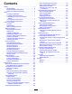
Safety • Keep clear of any discharge opening. Keep This machine has been designed in accordance with ANSI B71.4-2017. • Keep children out of the operating area. Never bystanders and pets a safe distance away from the machine. allow children to operate the machine. • Stop the machine, shut off the engine, remove the General Safety key, and wait for all moving parts to stop before servicing, fueling, or unclogging the machine.
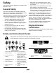
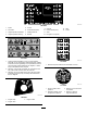
decal106-9290 106-9290 1. Inputs 5. In seat 2. Not active 6. Power takeoff (PTO) 9. Outputs 14. Power 10. Power takeoff (PTO) 3. High temperature shutdown 7. Parking brake off 11. Start 4. High temperature warning 12. Energize to run (ETR) 8. Neutral 13. Start decal107-1866 107-1866 decal110-9796 1.
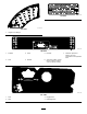
decal133-5618 133-5618 decal120-9164 120–9164 1. Height-of-cut settings decal120-9196 120-9196 1. Forward 3. Slow 5. Reverse 2. Fast 4. Neutral 6. Tow valve location; torque the tow valves to 5.65 to 7.91 N∙m (50 to 70 in-lb). 7. Read the Operator's Manual for more information on the hydraulic fluid. decal121-3363 121–3363 1. Fast 3. Engage PTO 2. Slow 4.
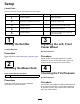
Setup Loose Parts Use the chart below to verify that all parts have been shipped. Procedure 1 2 3 4 5 Description No parts required – Raise the ROPS. Mower deck Installation Instructions 1 Install the mower deck. No parts required – Adjust the left, front caster wheel. No parts required – Check the tire pressure. No parts required – Check the hydraulic fluid, engine oil, and coolant levels.
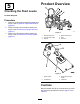
Product Overview 5 Checking the Fluid Levels No Parts Required Procedure 1. Check the hydraulic-fluid level before starting the engine, refer to Hydraulic System Maintenance (page 60). 2. Check the engine-oil level before starting the engine, refer to Checking the Engine-Oil Level (page 47). 3. Check the cooling system before starting the engine; refer to Checking the Cooling System (page 53). g020877 Figure 3 1. Parking brake lever 4. Motion control lever 2. Fuel cap (both sides) 5. Seat 3.
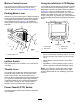
Motion-Control Levers Using the InfoCenter LCD Display The motion-control levers control the forward and rearward motions as well as the turning of the machine. Refer to Driving the Machine (page 23). The InfoCenter LCD display shows information about your machine such as the operating status, various diagnostics and other information about the machine (Figure 6). There is a splash screen and main information screen of the InfoCenter.
InfoCenter Icon Description InfoCenter Icon Description (cont'd.) SERVICE DUE Indicates when scheduled service should be performed RPM Engine RPM/status—indicates the engine RPM Operator must release switch Hour meter Operator should change to indicated state Symbols are often combined to form sentences.
Service Menu Item Description Hours Lists the total number of hours that the machine, engine and fan have been on, as well as the number of hours the machine has been transported and has overheated. Settings Menu Item Description Units Controls the units used on the InfoCenter. The menu choices are English or Metric Language Controls the language used on the InfoCenter*. LCD Backlight Controls the brightness of the LCD display. LCD Contrast Controls the contrast of the LCD display.
Protected Menus 3. To enter the PIN code, press the center button until the correct first digit appears, then press the right button to move on to the next digit (Figure 8B and Figure 8C). Repeat this step until the last digit is entered and press the right button once more. 4. Press the middle button to enter the PIN code (Figure 8D).
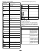
Specifications g242498 Figure 9 Description Figure 9 reference Dimension or Weight Height with roll bar up C 183 cm (72 inches) Height with roll bar down D 125 cm (49 inches) Overall length F 253 cm (99-1/2 inches) Overall width B 145 cm (57 inches) Wheel base E 145 cm (57-1/4 inches) Wheel tread (tire center to center) rear A 114 cm (45 inches) 13
Ground clearance 10 cm (4 inches) Weight, with 72-inch Side-Discharge Mower (30354 or 30481) 1052 kg (2,320 lb) Weight, with 60-inch Side-Discharge Mower (30456) 1036 kg (2,284 lb) Weight, with 72-inch Base Mower Deck (30353) 1012 kg (2,231 lb) Weight, with 62-inch Base Mower Deck (30457) 990 kg (2,183 lb) Weight with the 100-inch Rear-Discharge Mower (31101) 1200 kg (2,646 lb) change without notice.
• Do not store the machine or fuel container where Fuel Table there is an open flame, spark, or pilot light, such as on a water heater or other appliance. Diesel fuel specification Location ASTM D975 • If you spill fuel, do not attempt to start the engine; No. 1-D S15 avoid creating any source of ignition until the fuel vapors have dissipated. USA No. 2-D S15 Adding Fuel Fuel Specification EN 590 European Union ISO 8217 DMX International JIS K2204 Grade No.
Adjusting the Roll Bar Filling the Fuel Tank Important: The fuel tanks are connected, but the fuel does not transfer quickly from one tank to the other. It is important when filling that you park on a level surface. If you park on a hill, you may inadvertently overfill the tanks. WARNING To avoid injury or death from rollover, keep the roll bar in the raised locked position and use the seat belt. Important: Do not overfill the fuel tanks. Ensure that the seat is secured with the seat latch.
Raising the Roll Bar Raise the roll bar as shown in Figure 11. g031636 g031636 g031635 Figure 11 g031631 Note: Secure the roll bar so that it does not damage Figure 12 the hood. Important: Always use the seat belt when the roll bar is in the raised and locked position. Do not use the seat belt when the roll bar is in the lowered position.
Using the Safety-Interlock System Adjusting the Height of Cut You can adjust the height of cut from 2.5 to 15.8 cm (1 to 6 inches) in 6 mm (1/4 inch) increments by relocating the stop pin into different hole locations. 1. With the engine running, push the deck-lift switch up until the mower deck is fully raised and release the switch immediately (Figure 24). 2. Rotate the stop pin until the roll pin in it lines up with the slots in the holes in the height-of-cut bracket and remove it (Figure 13). 3.
position. Start the engine. While the engine is running, release the parking brake, engage the PTO, and rise slightly from the seat; the engine should shut off within 2 seconds. 4. Without an operator on the seat, engage the parking brake, move the PTO switch to the OFF position, and move the motion-control levers to the NEUTRAL-LOCK position. Start the engine. While the engine is running, center either motion control; the engine should shut off within 2 seconds. Repeat for the other motion-control lever.
Changing the Seat Suspension During Operation During Operation Safety The seat is adjustable to provide a smooth and comfortable ride. Position the seat where you are most comfortable. General Safety • The owner/operator can prevent and is responsible To adjust it, turn the knob in front either direction to provide the best comfort (Figure 17). • • • • g019768 • Figure 17 1.
Rollover Protection System (ROPS) Safety – Disengage the power takeoff and lower the attachments. – Engage the parking brake. • Do not remove the ROPS from the machine. • Ensure that the seat belt is attached and that you – Shut off the engine and remove the key. can release it quickly in an emergency. – Wait for all moving parts to stop. • Check carefully for overhead obstructions and do • Do not operate the machine when there is the risk of lightning.
Releasing the Parking Brake Tall grass can hide obstructions. Uneven terrain could overturn the machine. • Be aware that operating the machine on wet grass, across slopes, or downhill may cause the machine to lose traction. Loss of traction to the drive wheels may result in sliding and a loss of braking and steering. • Use extreme caution when operating the machine near drop-offs, ditches, embankments, water hazards, or other hazards.
2. Move the levers to the center, unlocked position. 3. Drive the machine as follows: • To move straight forward, slowly push the motion-control levers forward (Figure 22). • To move straight rearward, slowly pull the motion-control levers rearward (Figure 22). • To turn, slow the machine by pulling back on both levers and then push forward on the lever on the opposite side from which you want to turn (Figure 22). • To stop, pull the motion-control levers to the NEUTRAL position.
Shutting Off the Engine CAUTION Children or bystanders may be injured if they attempt to move or operate the tractor while it is unattended. Always remove the ignition key and engage the parking brake when leaving the machine unattended, even if just for a few minutes.
Operating the Mower Engaging the Power Takeoff (PTO) Using the Deck-Lift Switch The power-takeoff (PTO) switch starts and stops the mower blades and some powered attachments. Note: If the engine is cold, allow the engine to warm The deck-lift switch raises and lowers the mower deck (Figure 24). The engine must be running for you to use this lever. up 5 to 10 minutes before engaging the PTO. g243799 Figure 25 Disengaging the PTO g009174 Figure 26 g020873 Figure 24 1.
Cutting Grass with the Machine Diesel Particulate Filter Regeneration Note: Cutting grass at a rate that loads the engine The diesel particulate filter (DPF) is part of the exhaust system. The diesel-oxidation catalyst of the DPF reduces harmful gasses and the soot filter removes soot from the engine exhaust. promotes DPF regeneration. 1. Move the machine to the job site. 2. Whenever possible, set the throttle to high idle. 3. Engage the PTO switch. 4.
DPF Soot Accumulation • DPF regeneration is a process that heats the DPF to convert the soot to ash. • Over time, the diesel particulate filter accumulates • In addition to the warning messages, the computer soot in the soot filter. The computer for the engine monitors the soot level in the DPF. reduces the power produced by the engine at different soot-accumulation levels. • When enough soot accumulates, the computer informs you that it is time to regenerate the DPF.
DPF Ash Accumulation • When enough ash accumulates, the engine • The lighter ash is discharged through the exhaust system; the heavier ash collects in the soot filter. • Ash is a residue of the regeneration process. Over • time, the diesel particulate filter accumulates ash that does not discharge with the engine exhaust. • • The computer for the engine calculates the amount of ash accumulated in the DPF.
Types of Diesel Particulate Filter Regeneration Types of diesel particulate filter regeneration that are performed while the machine is operating: Type of Regeneration Conditions that cause DPF regeneration DPF description of operation Passive Occurs during normal operation of the machine at high-engine speed or high-engine load • The InfoCenter does not display an icon indicating passive regeneration.
Types of diesel particulate filter regeneration that require you to park the machine: (cont'd.) Type of Regeneration Conditions that cause DPF regeneration DPF description of operation Recovery Occurs because the operator ignored requests for a parked regeneration and continued operating the machine, adding more soot to the DPF • When the reset-standby/parked or recovery regeneration icon or ADVISORY #190 displays in the InfoCenter, a recovery regeneration is requested.
press the right button to select the Technician entry (Figure 34). DPF Operation Table (cont'd.) State Description Reset Regen The engine computer is running a reset regeneration. Parked Stby The engine computer is requesting that you run a parked regeneration. Parked Regen You initiated a parked regeneration request and the engine computer is processing the regeneration. Recov. Stby The engine computer is requesting that you run a recovery regeneration. Recov.
Assist DPF Regeneration • The icon displays in the InfoCenter while the reset regeneration is processing. • The engine computer adjusts engine settings to • Whenever possible, do not shut off the engine or raise the exhaust temperature. reduce engine speed while the reset regeneration is processing. • While operating the machine, run the engine at full engine speed and high load when possible to promote DPF regeneration.
g227304 g224394 Figure 39 2. Figure 41 Press the right button to change the inhibit regeneration setting from On to Off (Figure 39) or from Off to On (Figure 40). Note: If the engine exhaust temperature is too low, the InfoCenter displays ADVISORY #186 (Figure 42) to inform you to set the engine to full throttle (high idle).
Parked or Recovery Regeneration Recovery Regeneration Messages • When the engine computer requests either a When a recovery regeneration is requested by the engine computer, the following messages display in the InfoCenter: parked regeneration or a recovery regeneration, the regeneration request icon (Figure 43) displays in the InfoCenter.
1. Access the DPF Regeneration menu, press the center button to scroll down to either the PARKED REGEN START option or the RECOVERY REGEN START option (Figure 50), and press the right button to select the start the regeneration (Figure 50). g224628 Figure 49 Preparing to Perform a Parked or Recovery Regeneration 1.
g224414 g224626 g227678 g224630 Figure 51 3. Figure 53 At the DPF checklist screen, verify that the parking brake is engaged and that the engine speed is set to low idle (Figure 52). 5. The InfoCenter displays the INITIATING DPF REGEN message (Figure 54). g224411 g227681 Figure 54 6. g224407 g227679 Figure 52 4. At the INITIATE DPF REGEN screen, press the right button to continue (Figure 53). 36 The InfoCenter displays the time to complete message (Figure 55).
Check Message and Corrective Action Table (cont'd.) g224406 Corrective Action: Change the engine speed to low idle. g224406 Figure 55 7. The engine computer checks the engine state and fault information. The InfoCenter may display the following messages found in the table that follows: Corrective Action: Troubleshoot the engine computer condition and retry DPF regeneration. 8.
Canceling a Parked or Recovery Regeneration Use the Parked Regen Cancel or Recovery Regen Cancel setting to cancel a running parked or recovery regeneration process. 1. Access the DPF Regeneration menu (Figure 59). g224392 Figure 57 Note: If the regeneration fails to complete, the InfoCenter displays Advisory #184 (Figure 57). Press the left button to exit to the home screen. g227305 Figure 59 2.
Operating Tips inside the mower, cutting quality eventually becomes unsatisfactory. Fast Throttle Setting/Ground Speed To reduce the risk of fire hazard, keep the engine, muffler, battery compartment, parking brake, cutting units, and fuel storage compartment free of grass, leaves, or excessive grease. Clean up any spilled oil or fuel. To maintain enough power for the machine and deck while mowing, operate the engine at the FAST throttle position and adjust your ground speed for conditions.
Transporting the Machine Important: Always push the machine by hand and never a long distance. Never tow the machine, because damage to the hydraulic system may occur. Use a heavy-duty trailer or truck to transport the machine. Ensure that the trailer or truck has all the necessary brakes, lighting, and marking as required by law. Please carefully read all the safety instructions. Knowing this information could help you, your family, pets, or bystanders avoid injury.
Loading the Machine Use extreme caution when loading or unloading machines onto a trailer or a truck. Use a full-width ramp that is wider than the machine for this procedure. Drive the machine up ramps in reverse and drive it down ramps in a forward direction (Figure 63). g027995 Figure 63 1. Drive the machine up the ramp in reverse. 2. Drive the machine forward down the ramp. Important: Do not use narrow individual ramps for each side of the machine.
Maintenance Note: Determine the left and right sides of the machine from the normal operating position. Important: Refer to your engine owner’s manual Note: Download a free copy of the electrical or for additional maintenance procedures. hydraulic schematic by visiting www.Toro.com and searching for your machine from the Manuals link on the home page. Recommended Maintenance Schedule(s) Maintenance Service Interval Maintenance Procedure After the first 10 hours • Torque the frame-mounting bolts.
Daily Maintenance Checklist Duplicate this page for routine use. Maintenance Check Item For the week of: Mon. Tues. Wed. Thurs. Fri. Check the safety-interlock operation. Check the grass deflector in the down position (if applicable). Check the parking-brake operation. Check the fuel level. Check the hydraulic fluid level. Check the engine-oil level. Check the cooling-system fluid level. Check the drain water/fuel separator. Check the air-filter restriction indicator.
CAUTION If you leave the key in the ignition switch, someone could accidently start the engine and seriously injure you or other bystanders. Remove the key from the ignition before you do any maintenance. Lubrication Pre-Maintenance Procedures Greasing the Bearings and Bushings Important: The fasteners on the covers of this machine are designed to remain on the cover after removal.
4. Move the throttle lever to the SLOW position, shut off the engine, remove the key, and wait for all moving parts to stop before leaving the operating position. 5. Lift the footrest, exposing the top of the mower deck. 6. Remove the dipstick/fill plug from the top of the gearbox and make sure that the lubricant is between the marks on the dipstick (Figure 65). 6. Remove the dipstick/fill plug from the top of the gearbox (Figure 65). 7.
Engine Maintenance Note: If the foam gasket in the cover is damaged, Engine Safety Important: Avoid using high-pressure air, which could force dirt through the filter into the intake tract. replace it. • Shut off the engine and remove the key before checking the oil or adding oil to the crankcase. Important: Do not clean the used filter to avoid damage to the filter media. • Do not change the governor speed or overspeed the engine. Important: Do not use a damaged filter.
Servicing the Engine Oil Oil Specification Use high-quality, low-ash engine oil that meets or exceeds the following specifications: • API service category CJ-4 or higher • ACEA service category E6 • JASO service category DH-2 Important: Using engine oil other than API CJ-4 or higher, ACEA E6, or JASO DH-2 may cause the diesel particulate filter to plug or cause engine damage. g020435 Figure 68 Use the following engine oil viscosity grade: 1.
g214715 g213864 g021890 Figure 69 1. Oil-drain plug g213863 Figure 71 2. Oil filter 2. Remove the oil filter (Figure 69). Apply a light coat of clean oil to the new filter seal before screwing it on. Do not overtighten. 3. Add oil to the crankcase; refer to Checking the Engine-Oil Level (page 47).
Fuel System Maintenance Note: Refer to Fuel Specification (page 15) for proper fuel recommendations. DANGER Under certain conditions, diesel fuel and fuel vapors are highly flammable and explosive. A fire or explosion from fuel can burn you and others and can cause property damage. • Use a funnel and fill the fuel tank outdoors, in an open area, when the engine is off and is cold. Wipe up any fuel that spills. • Do not fill the fuel tank completely full.
Cleaning the Fuel Tank Electrical System Maintenance Service Interval: Every 2 years Remove and clean the in-line strainers after draining the tank. Use clean diesel fuel to flush out the tank. Electrical System Safety Important: Drain and clean the tank if the fuel system becomes contaminated or if you are storing the machine for an extended period.
Note: If a fuse blows frequently, you may have a WARNING short in the electrical system and should have it serviced by a qualified service technician. Battery terminals or metal tools could short against metal machine components causing sparks. Sparks can cause the battery gasses to explode, resulting in personal injury. • When removing or installing the battery, do not allow the battery terminals to touch any metal parts of the machine.
Drive System Maintenance Checking the Tire Pressure Service Interval: Every 50 hours/Monthly (whichever comes first) Maintain the air pressure in the front and rear tires (Figure 76). The correct air pressure is 124 kPa (15 psi) in the rear tires and 103 kPa (25 psi) in the caster wheels. Uneven tire pressure can cause an uneven cut. Note: Check the tires when they are cold to get the most accurate pressure reading. g004760 Figure 77 1. Locknut 6. Spacer 2. Bearing spacer 7. Caster wheel 3.
Cleaning the Radiator Cooling System Maintenance Service Interval: Before each use or daily Every 1,500 hours—Replace moving hoses. Cooling System Safety Every 200 hours—Inspect the cooling-system hoses and seals. Replace them if cracked or torn. • Swallowing engine coolant can cause poisoning; keep out of reach from children and pets. Every 2 years—Flush and replace the cooling-system fluid.
Brake Maintenance 4. Adjusting the Parking-Brake Interlock Switch 1. 2. Move the switch up or down on the bracket until the distance between the brake-shaft sensor and the switch plunger is 4 mm (5/32 inch) as shown in Figure 80. Note: Make sure that the brake-shaft sensor does not contact the switch plunger. Stop the machine, move the motion-control levers to the NEUTRAL-LOCK position, engage the parking brake, and remove the ignition key. 5. Secure the switch jam nuts. 6.
Belt Maintenance Controls System Maintenance Checking the Alternator-Belt Tension Adjusting the Control-Lever Neutral-Interlock Switch Service Interval: Every 100 hours 1. Apply 44 N (10 lb) of force to the alternator belt, midway between the pulleys. 2. If the deflection is not 10 mm (3/8 inch), loosen the alternator mounting bolts (Figure 81). 1. Stop the machine, move the motion-control levers to the NEUTRAL-LOCK position, engage the parking brake, and remove the ignition key. 2.
g020875 Figure 84 1. Bolt 2. Control panel g004763 Figure 83 1. Control lever 2. Neutral-interlock switch 3. Screw 4. 0.4 to 1 mm (0.015 to 0.045 inch) 4. Holding the control lever against the frame, move the switch toward the lever until the distance between the lever and switch body is 0.4 to 1 mm (0.015 to 0.045 inch) as shown in Figure 83. 5. Secure the switch. 6. Repeat steps 3 to 5 for the other lever. 7. Install the front panel. 4.
WARNING The engine must be running to perform this adjustment. Contact with moving parts or hot surfaces may cause personal injury. Keep hands, feet, face, clothing, and other body parts away from rotating parts, muffler, and other hot surfaces. g004918 1. Raise the frame onto stable jack stands so that the drive wheels can rotate freely. 2. Slide the seat forward, unlatch it, and swing it up and forward. 3. Disconnect the electrical connector from the seat safety switch. 4.
WARNING The electrical system does not perform proper safety shutoff with the jumper wire installed. • Remove the jumper wire from the wire harness connector and plug the connector into the seat switch when you complete adjustment. • Never operate the machine with the jumper installed and the seat switch bypassed. 13. Lower the seat into position. 14. Remove the jack stands. Adjusting the Maximum Ground Speed 1.
Adjusting the Tracking 1. Disengage the PTO, move the motion-control levers to the NEUTRAL-LOCK position, and engage the parking brake. 2. Move the throttle lever to the SLOW position, shut off the engine, remove the key, and wait for all moving parts to stop before leaving the operating position. 3. Loosen the bolts securing the control levers (Figure 90). g004766 Figure 89 1. Stop bolt 3. Jam nut 2. Control lever 4. 1.5 mm (0.060 inch) 5.
Hydraulic System Maintenance The reservoir is filled at the factory with approximately 4.7 liters (5 quarts) of high quality tractor transmission/hydraulic fluid. The recommended replacement fluid is as follows: Toro Premium Transmission/Hydraulic Tractor Fluid (Available in 5 gallon pails or 55 gallon drums. See parts catalog or Toro distributor for part numbers.) Alternate fluids: If the Toro fluid is not available, Mobil® 424 hydraulic fluid may be used.
3. Raise the deck to extend the lift cylinders, shut off the engine, and remove the key. 4. Raise the seat to access the hydraulic fluid tank. 5. Remove the hydraulic fill cap from the filler neck (Figure 92). Changing the Hydraulic Fluid and Filter Service Interval: After the first 200 hours Every 800 hours 1. Disengage the PTO, move the motion-control levers to the NEUTRAL-LOCK position, and engage the parking brake. 2.
Cleaning Storage Cleaning Under the Mower Machine 1. Service Interval: Before each use or daily 1. Disengage the PTO, move the motion-control levers to the NEUTRAL-LOCK position, and engage the parking brake. 2. Move the throttle lever to the SLOW position, shut off the engine, remove the key, and wait for all moving parts to stop before leaving the operating position. 3. Raise the mower to the transport position. 4. Raise the front of the machine using jack stands. 5.
8. Service the battery and cables as follows: A. Remove the battery terminals from the battery posts. B. Clean the battery, terminals, and posts with a wire brush and baking soda solution. C. Coat the cable terminals and battery posts with Grafo 112X skin-over grease (Toro Part No. 505-47) or petroleum jelly to prevent corrosion. D. Slowly recharge the battery for 24 hours every 60 days to prevent lead sulfation of the battery. Engine 1.
Notes:
Notes:
Notes:
California Proposition 65 Warning Information What is this warning? You may see a product for sale that has a warning label like the following: WARNING: Cancer and Reproductive Harm—www.p65Warnings.ca.gov. What is Prop 65? Prop 65 applies to any company operating in California, selling products in California, or manufacturing products that may be sold in or brought into California.
The Toro Warranty A Two-Year Limited Warranty Conditions and Products Covered The Toro Company and its affiliate, Toro Warranty Company, pursuant to an agreement between them, jointly warrant your Toro Commercial product (“Product”) to be free from defects in materials or workmanship for two years or 1500 operational hours*, whichever occurs first. This warranty is applicable to all products with the exception of Aerators (refer to separate warranty statements for these products).