FORM NO. 3316 -390 Rev. B SIDE DISCHARGE MODEL: 30722 ~ 40007 THRU 50001 & Up OPERATOR'S REAR DISCHARGE MODEL: MANUAL A0710 ~ 40007 THRU 50001 & UP 727 CUTTING UNITS j FOR GROUNDS MASTER 300 SERIES TRACTION UNITS To assure maximum safety, optimum performance, . and to gal knowledge of the product, iris essential mRO that you or any other operator of the machine read and understand the contents of this manual before THIS UNIT CONFORMS TO the engine is ever started.
FOREWORD The cutting units have advanced concepts in engineering, design and safety; and if maintained properly, they will give excellent service. Since they are high-quality products, Toto is concerned about the future use of the machines and safety of the user, Therefore, read this manual to familiarize yourself with proper set-up, operation and maintenance instructions. The major sections of the manual are: 1. Safety instructions 3. Before Operating 5. Maintenance 2. Set-up Instructions 4.
SAFETY INSTRUCTIONS 5. Keep all shields and safety devices in place. If 2 shield, safety device or decal is damaged, malfunctioning, or illegible, repair or replace it before operation is commenced. Also tighten loose nuts, bolts and screws to ensure machine is in safe operating condition. 6. Do not operate machine while wearing sandals, tennis shoes, sneakers or shorts. Also, do not wear loose fitting clothing which could get caught in macing parts. Always wear long pants and substantial shoes.
SAFETY INSTRUCTIONS 18. Cut grass slopes carefully. Do not start, stop, or turn suddenly when traveling uphill or downhill. 20. Do not touch engine, muffler or radiator while engine is running or soon after it is stopped. These areas could be hot enough to cause a burn, 21. Before getting off the seat A. Move traction pedal to neutral position and remove foot from pedal. B. teethe parking brake and disengage the PTO. C. Shut the engine off and remove key from ignition switch.
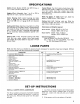
SPECIFICATIONS Width of Cut: Models 30722 and 30710 have a 71-1/2 inch (1.816 m} width of cut. Height-of-Cut: Adjustable from 102 mm} in 1/2in. {13 mm) increments. Cutter Housing: Both cutter housings are made from 11 gauge {13 mm} steel and reinforced with 3-1/2 inch (88 mmj x 7 gauge (4.76 mm) channel iron. Cutting Unit Drive: Gear box mounted on cutting unit is driven by PTO shaft, Power is transmitted to the blades by three B section belts.
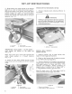
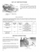
SET-UP INSTRUCTIONS 3. Slide spacers onto caster spindle to get desired height-of-cut: refer to Height-of-Cut Chart, page 10 Slide thrust washer onto spindle, push large caster spindle through front caster arm and small caster spindle through rear caster arrant, install remaining spacers onto spindle and install lynch pin to secure assembly (Fig. 1, 2}, Figure 1 1. Lynch pin 3. Th east washer 2. Spacers 4.
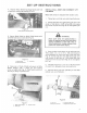
SET-UP INSTRUCTIONS 4. Position Belly Shield mounting hooks over hub of push arm mounting brackets {Fig. b}, Figure 5 1. Befit shield mounting hooks 5. Secure Belly Shield to Belly Shield hooks with (2} /16 lockouts on each side (Fig, 6). Figure 8 1. Betty shied 2. Betsy shield hank 3. Lookouts 6. Raise rear of Belly Shield and secure to Belly Shield hangers with 2 clevis pin and hairpin cotter on each side {Fig. 7). Push hairpin cotter all the way to loop, to prevent Jose. figure 7 1.
SET-UP INSTRUCTIONS 7. Raise front of lift arm until hole in movable end of cylinder fines up with holes in §ift arm brackets. Use caution as lift earn is spring-loaded. Hold parts together with cylinder pin, spring pin, and WARNING cotter pin. Cotter pin must be to the outside. Since the right hand push arm is spring toadied to about 100 pounds (445 M), a helper is beaded to push the push arm down. Sudden reseals of the push arm could cause injury, 3.
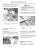
SET-UP INSTRUCTIONS PP A WARNING Since left hand push arm is spring loaded to about 150 pounds (667 N) a helper is needed to push down on-the push arm, Sudden release of the push arm could cause injury. 2. Have a helper carefully push down on the push arm until ball joint mount contacts front of mount bracket on cutting unit. Immediately slide {102 x 102 mm) block of wood between top of push arm and underside of chassis. A Make sure the wooden block does not slip out accidentally.
SET-UP INSTRUCTIONS GREASE CUTTING UNIT Before the machine is operated, it must be greased 1o assure proper lubricating characteristics: refer e Lubrication, page 12. Failure to grease the machine will result in premature failure of derivative parts. 1. PO shield 4. Spring in dth link 2. Eff-tapping screws 5, Spring in cotter pin 3 Lift chain INSTALL REAR WEIGHT Two Wheel Drive Grounds master 300 Series Traction Units comply with ANSI Standard when equipped with rear weight.
OPERATING INSTRUCTIONS ADJUSTING HEIGHT-OF-CUT The height-of-cut is adjustable from 1 to 4 inches {25 16 102 mm) in 1/2 inch {13 rim) increments, by adding or removing an equal number of spacers on the front and rear caster forks, The height-of cut chart below gives the combinations of spacers 10 use for all bright-of-cut settings. Mote: 1/4 inch (68 mm} spacers are available and can be ordered from your Tore distributor by Toto Part No. 27-1040. {Quantity 8).
LUBRICATION MAINTENANCE GREASING BEARINGS, BUSHINGS AND GEAR BOX The cutting unit must be lubricated regularly. 1f machine is operated under normal conditions, lubricate caster bearings and bushings with No. 2 general purpose lithium grease or molybdenum base grease, after every 8 heirs of operation or daily, whichever comes first. All other bearings, bushings and the gear box must be lubricated after every 50 hoers of operation. 1.
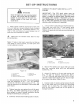
CUTTING UNIT MAINTENANCE SEPARATING CUTTING UNIT FROM TRACTION UNIT 1. Position making on level surface, lower cutting unit to the shop floor, shut engine off and engage parking brake. 2. Remove self-tapping screws securing shield 1o top of cutting unit and set shield aside. 3. Drive role pin out of yoke and input shaft of gear box (Fig. 24). Also, loosen cap screws and lockouts. Slide yoke off the input shaft.
CUTTING UNIT MAINTENANCE 4. Have a helper carefully push down on right hand push arm until holes in ball joint mount ling up with holes in caster arm. Secure ball joint mount to caster arm with two cap screws w/large Dishwashers, one flat washer {15/32 1.D. x 59/64 in. (234 mm} O.D), wo lock washers and nuts {7/16 14). Heads of cap screws and large flat washers must be on outside of caster arm. 6. Slide Dishwashers (15/32 1.0, x b9/64 in. (23.4 mm} 0.0 onto two cap screws (7/16 in,) (76 mm). 8.
CUTTING UNIT MAINTENANCE 6. Inspect caster spindle for wear and replace it if damaged, 7. Push caster spindle through bushings and mounting tube. Slide spacers onto spindle. Install NEH pin through caster spindle to retain all parts in place. SERVICING REAR CASTER WHEEL AND BEARING The rear caster wheels rotate on high-quality roller bearings which are supported by spanner bushings. Even after many hours of use, provided that the bearing was kept well-lubricated, bearing wear will be minimal.
CUTTING UNIT MAINTENANCE bushing into open end of wheel hub to captivate the bearing inside the wheel hub 8. Carefully slide spanner through the bushings and wheel hub. 7. Install caster wheel assembly and {2} washers between caster fork, and secure all parts in place with cap screw and lockout. 8. Lubricate caster whee! bearing through grease fitting, using No. 2 general purpose lithium grease.
CUTTING UNIT MAINTENANCE SHARPEN AT ORIGINAL ANGLE: L END VIEW Figure 32 4. To check bleed for being straight and parallel, lay blade on level surface and check its ends. Ends of blade must be slightly lower than the center, and cutting edge must be lower than heel of the blade, This blade will produce good quality-of-cut and require minimal power from the engine.
IDENTIFICATION AND ORDERING MODEL AND SERIAL NUMBERS The cutting unit has two identification numbers: a model number and a serial number. These numbers are stamped into a plate. The cutting unit identification plate is located just ahead of the left rear caster wheel (Fig. 33). In any correspondence concerning the cutting unit, supply the model and serial numbers to assure correct information and replacement parts are obtained.
CARPAL DR VWY Commercial Products tf you feel your TOR product is defective and wish 1o rely on The Toto Promise, the following procedure is recommended: 1. Contact your Authorized TOR Distributor or Commercial Dealer {the Yellow Pages of your telephone directory is a good reference source), . The TOR Distributor or Commercial Dealer will advise you on the arrangements that can be made o inspect and repair your product. .