FORM HO. 3313-249 CUTTING UNIT MODEL: COOPERATOR'S 30716 — BOOTH & UP MANUAL TRIFLE 88" CUTTING UNIT FOR GROUNDWATER 322-D & 327 TOR B T TO AHSIB71.4 < 1984 To assure maximum safety, optimum performance, and to gain knowledge of the product, it is essential that you or any wither operator of the mower read and understand the contents of this manual before the engine is ever started.
FORWARD The 88" cutting unit has advanced concepts in engineering, design and safety, and if maintained properly, wail give excellent service. Since it is a high quality product, Teri is concerned about the future use of the machine and safety of the user. Therefore, read this manual to familiarize yourself with proper set-up, operation and maintenance instructions. The major sections of the manual are: 5. Lubrication Maintenance 8. Cutting Unit Maintenance 1. Batty Instructions 2. Set-up Instructions 3.
SAFETY INSTRUCTIONS 4. Keep all shields and safety devices in place. if a shield, safety device or decal is defective or damaged, repair or replace it before operating machine. Also tighten any loose nuts, bolts and screws lo assure the machine is in a safe operating condition. 5. Do not operate machine while wearing sandals, tennis shoes, sneakers or shorts, Also, do not wear loose fitting clothing which could get caught in moving parts. Always wear dong pants and substantial shoes.
SAFETY INSTRUCTIONS throttle to SLOW, set parking brake and shut engine off. Remove key from switch to prevent possibility of accidental starting. Check cutting unit and traction unit for damage and defective parts. Repair any damage before restarting the engine and operating the cutting unit. Be sure blades are in good condition and blade bolts are tight. 22. Cut grass slopes carefully. Do not start, stop, or turn suddenly. Be sure 1o lower the deck to the ground before going down a slope. 23.
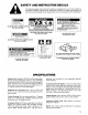
SAFETY AND INSTRUCTION DECALS The following safety and instruction decals are installed on the unit. If any become damaged or illegible, replace them. Decal part numbers are listed under decals and also in your parts catalog. Order replacements from your Authorized Toto Distributor. WARNING SPINE LADED MECHANISMS S PIRATICAL S MAIN FOR HOARSELY CONGEAL ON MAIN DECK, UNDER COVER (Part No. 556-4300) A WARNING ROTATING BLADES UNDER ENTIRE MOWER DECK KEEP HANDS and FEET AWAY THROWN OBJECTS ABE DANGEROUS.
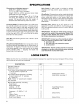
SPECIFICATIONS Dimensions and Weights (approx.}: Width: 83 in. {236 cm} overall 73 1/2 in. {186.7 cm} in transport Weight: 600 Ibs. {272.4 kg) plus tractor belly shield and three rear weights. Counterbalance Weight: Three, 35 1b. {15.9 kg) Tore Rear End Weights are required. Do not exceed 140 pounds total rear end weight or excessive rear axis bushing wear may occur. Trimming Ability: The deck is offset the right of center line of machine.
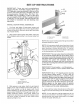
SET-UP INSTRUCTIONS IMPORTANT: Three rear end counterbalance weights {Part No. 24-5790) weighing 35 [b. sate {18.9 ky) each, must be attached to the rear of the traction unit before the deck is installed. The Toto Grounds master Weight Box Kit (Part No. $2-G590) may be installed, in place of the thees rear end weights, weight is added ta the box, Do not exceed 140 total pounds rear end weight or excessive rear axle bushing wear may scour, INSTALL CASTER WHEEL ASSEMBLIES 1.
SET-UP INSTRUCTIONS Figure 3 17U spacers (6] 3. Cortes whee ate hoes 2. Spacers opening 4. Mechanical door 5. Place the rear axles into the lower caster fork holes for higher height-of-cut settings {above 1% or 28mmj where optimum cutting appearance is not required. INSTALL BELLY SHIELD 1. Position inaction unit on level surface, shut engine off and engage parking brake. 2. Bi lock up the forward end of engine {gasoline only) o prevent it from shifting during disassembly. 3.
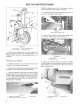
SET-UP INSTRUCTIONS CONNECT LEFT HAND PUSH ARM TO CUTTING UNIT A WARNING Since left hand push arm is spring loaded to about 180 pounds (667 Nj a helpers needed to push down on the push arm. Sudden release of the push arm could cause injury. 1. Slide deck under front of traction unit. 2. To assure correct deck alignment, loosen the push arm ball joint knockout and measure from the end of the push arm to the center-line of the ball joint and adjust to 2 3/8" {60 8). Leave the push arm lockout loose.
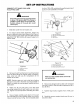
SET-UP INSTRUCTIONS CONNECT RIGHT HAND PUSH ARM TO CUTTING UNIT o fi WARNING Since the right hand push arm is spring loaded to about 100 pounds (445 N), a helper is nestled to push the push arm down. Sudden release of the push arm could cause injury. MOTE: Remove right hand wing cover and then remove center right cover, 1. Toes sure correct alignment, loosen the push arm ball joint lock nut and measure from the end of the push arm to the center line of the ball joint and adjust to 2 3/8”.
SET-UP INSTRUCTIONS Figure 13 7. PTO shield mounting craws IMPORTANT: Improper chain adjustment could result in main deck ift arm damage if deck contacts traction unit, Mote: As starting points use the following settings: Right Front Chain — 10 links, lower bracket hole Left Front Chain — 14 links, lower hole Rear Chain — 10 links, upper and front holes 4.
BEFORE OPERATING 1 in. Height-of-Cut — Skids all the way up. 11/2 Height-of-Cut — Skids off the ground 2 1/2 . and higher Height-of-Cut — Skids all the way down. When height-of-cut is set 1/2” the center anti-scalp roller (Fig. 18)and the two ball rollers on the front of the deck should be in the upper position. When the height-of-cut is set the rollers should be in the lower position. Sy e Figure 16 7. Canter into suave taller 2.
OPERATING INSTRUCTIONS ADJUSTING HEIGHT-OF-CUT The height-of-cut is adjustable from 1 t0 4 inches {25 to 102Zmm) in 1/2 inch {13 mm} increments, by adding or removing an equal number of spacers on the front and rear caster forks. The height-of-cut chart below gives the combinations of spacers to use for all height-of-cut settings.
OPERATING INSTRUCTIONS 3. Push caster shaft through caster arm. Slide any refraining spacers onto shaft {Fig. 19 and 20). install lynch pin to retain parts in place. Always retain the same number of spacers on sate caster when adjusting height-of-cut. IMPORTANT: Al gix U shaped spacers must be on rear square caster shafts — If one is left off remaining spacers will not stay in position swing operation. Always install spacers on caster shafts with the spacer opening facing forward or to the rear (Fig. 20).
LUBRICATION MAINTENANCE The cutting unit must be lubricated regularly. {f machine is operated under normal conditions, lubricate caster bearings and bushings with No. 2 general purpose lithium grease or molybdenum has grease, after every 8 hours of operation or daily, whichever comes first. All other bearings, bushings and the gear box must be lubricated after every 50 hours of operation. 1.
LUBRICATION MAINTENANCE 2. Lower cutting units caster wheels are on a level surface. Remove filler plug (Fig. 27} from gear box and check level of lubricant. i level of lubricant is low add SAE 10W-30 or 10W-40 SE or SF engine oil until level is up to bottom of filler hole. Wipe any metal particles off filler plug and install filler plug. i Figure 27 1. Gear box magnetic 1l pig CUTTING UNIT MAINTENANCE SEPARATING CUTTING UNIT FROM TRACTION UNIT 1.
CUTTING UNIT MAINTENANCE 6. Have a helper push down on the right push arm while you remove the cap screws, flat washers and nuts securing ball joint mount to caster arm on cutting unit, Now the helper can carefully allow push arm to move upward, which gradually releases the 100 pounds (445 N} of spring load. 7. Have a helper push down on the left push arm while you remove the cap screws, flat washers and nuts securing ball joint mount to carrier frame on cutting unit.
CUTTING UNIT MAINTENANCE 3. Be sure all belt guides are correctly positioned and secured to the deck before operating the cutting unit. IMPORTANT: Greater than 3/ 16 in. gap between rubber stop and idle arm requires pretension of belt. IMPORTANT: Over pensioning of belts results in premature belt wear. REPLACING BLADE DRIVE BELTS Wing Sections: 1. Lower cutting unit to the shop orifice, turn off engine and remove key. Remove and set covers aside.
CUTTING UNIT MAINTENANCE MOTE: Idler arm assembly is shimmed 10 center the brake pad (Vertically} in the pulley groove. Add washers under the idler arm pivot hub as necessary. WING SHAFT END PLAY Slotted holes in the hinge bracket allow for adjustment of wing shaft end play (Fig. 33). End play should be no more than 1/16 inch. Figure 33 7. Slatted wing shaft bracket hinges 2.
CUTTING UNIT MAINTENANCE 1. Raise cutting unit to highest position, shut the engine off and engage parking brake. Block cutting unit to prevent it from falling accidentally. 2. Grasp end of blade using rag or thickly padded glove. Remove special screw, lock washer, anti scalp cup and blade from spindle assembly (Fig. 38}). Figure 36 1. Cutting tine 4. Flange obits (5) 2. Matting screw and Jock washer 5. Sp indite housing 3. Anti peals eop 3.
CUTTING UNIT MAINTENANCE 1. Position the deck on a flat 4 X 8 sheet of plywood at least 374" {20mm) thick. IMPORTANT: i the bear caster wheel axle is in the lower hole place a 3/4” block under each front caster wheel 1o level the deck. Thisisnotnecessary if the rear caster wheal axle is in the upper hole. 2. Adjust height-of-cut so all six height-of-cut spacers are below the caster arm {Highest height of-cut). 3. Lower cutting unit onto flat surface. 4.
IDENTIFICATION AND ORDERING MODEL AND SERIAL NUMBERS The cutting unit has two identification numbers: & model and a serial number. These numbers are stamped into a plate. The cutting unit identification plate is located just behind the left front hinge bracket. in any correspondence concerning the cutting unit, supply the model and serial numbers to assure correct information and replacement parts are obtained.
The Torn Promise A ONE YEAR LIMITED WARRANTY The Torah Company promises 1o repair your TOR Product if defective in materials ar workmanship. The following time periods from the die of purchase apply Commercial Products 1 Year The costs of pares and labor ave included, bue the customer pas the transportation costs moonwalk rotas I you feel your TOR product is defective and wish to rely on The Toto Promise, the following procedure is recommended: 1.