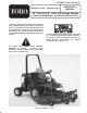
FORM NO. 3323-978 Rev B MODEL NO. 30799 - 200000001 & UP OPERATOR'S MANUAL 72” Flex Deck Side Discharge Mower FOR GROUNDSMASTER 300 SERIES TRACTION UNITS To ensure maximum safety, optimum performance, and to gain knowledge of the product, it is essential that you or any other operator of the machine read and understand the contents of this manual before the engine is ever started.
FOREWORD The 72" Flex Deck Side Discharge Mower has advanced concepts in engineering, design and safety; and if maintained properly, will give excellent service. Since this is a high-quality product, Toro is concerned about the future use of the machine and safety of the user. Therefore, read this manual to familiarize yourself with proper set-up, operation and maintenance instructions. The major sections of the manual are: 1. Safety Instructions 2. Set-up Instructions 3. Before Operating 4. Operation 5.
SAFETY INSTRUCTIONS The safety alert symbol means CAUTION, WARNING or DAN GER personal safety instruction". Read and under stand the instruction because it has to do with safety. Failure to comply with the instruction may result in personal injury. Hazard control and accident prevention are dependent upon the awareness, concern, and proper training of the personnel involved in the operation, transport, maintenance, and storage of the machine.
SAFETY INSTRUCTIONS D. Reduce speed when making sharp turns and when turning on hillsides. E. Avoid sudden starts and stops. F. Before backing up, look to the rear and ensure no one is behind the machine. G. Watch out for traffic when near or crossing roads. Always yield the right-of -way. 15. If engine stalls or machine loses headway and cannot make it to the top of a slope, do not turn machine around. Always back slowly straight down the slope. 16.
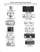
SAFETY AND INSTRUCTION DECALS The following decals are installed on the machine. If any become damaged or illegible, replace it. The decal part number is listed below and in your parts catalog. Replacements can be ordered from your Authorized Toro Distributor. ON LEFT CHAMBER COVER (Part No. 93-3709 ) ON FRONT NOSE OF EACH CHAMBER (Part No. 100-6582) LOCATED BY SPRINGS (Part No. 93-6696) ON RIGHT REAR HANGER, CENTER CHAMBER (Part No. 100-8038) ON FRONT CENTER OF EACH CHAMBER (Part No.
SPECIFICATIONS Width of Cut: 72" Configuration: Three blades, one blade center section, and two 1 blade floating wings. Wings flex up and down 12 degrees in a single plane perpendicular to from center section. Height of Cut: Adjustable front and rear, in .50 inch increments from 1 to 4 inches. Construction: 12-gauge steel, 5.25 inches deep, welded construction and reinforced with 10-gauge steel channels. Castor Wheels: Front: Four 8 inch pneumatic wheels with greaseable roller bearings.
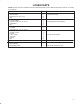
LOOSE PARTS NOTE: Use this chart as a checklist to ensure all parts have been received. Without these parts, total set-up cannot be completed. Description Hose Clamp Hose Bracket Capscrew 1/4-20 x 1" lg. Nut Push Arm Adapter Push Arm Plate Capscrew 3/8-16 x 2-3/4" lg. Flat Washer Nut Front Lift Arm Lock Nut Capscrew 1/2-13 x 3-1/2" lg. Rear Lift Bracket Square U-Bolt U-Bolt H.O.C. Chain Clevis Pin Hair Pin Nut Capscrew 3/8-16 x 7/8" lg. Operator's Manual Parts Catalog Registration Card Qty.
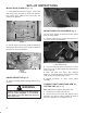
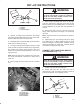
SET-UP INSTRUCTIONS MOUNT HOSE CLAMP (Fig. 1 -2) 1. Using dimensions shown in figure 1, locate, mark and drill (2) .280" dia. holes in traction unit platform. Use caution when drilling as there are hoses and cables under platform. 4.41" 1 Figure 3 1. grass Deflector MOUNT REAR CASTOR WHEELS (Fig. 4) .75" 12.75" The rear castor wheels are shipped secured upside down to deck brackets. 1. Remove capscrew and locknut securing front of rear castor pivot to deck bracket. Figure 1 2.
SET-UP INSTRUCTIONS WARNING 2 Since the right hand push arm is spring loaded to about 100 pounds, a helper is needed to push the arm down. Sudden release of the push arm could cause injury. 1 3 2-3/8" Figure 5 1. Ball joint 2. Jam nut 3. Push arm adapter 7. Have a helper carefully push down on the right push arm until holes in ball joint mount line up with holes in castor arm. Immediately slide a 4 x 4 in. block of wood between top of push arm and underside of chassis. 8.
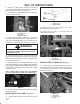
SET-UP INSTRUCTIONS 3. Remove (2) flange head capscrews and flange nuts securing left hand ball joint mount to castor arm. Remove ball joint mount from castor arm. 4. Install ball joint to left hand ball joint mount with a castle nut and cotter pin. 1 1 2 Figure 10 1. Traction T-bar 2. Rubber bumper 3 2 Figure 8 1. L.H. Push Arm 2. Ball joint 3. Ball Joint Mount 5. Have a helper carefully push down on the push arm until holes in ball joint mount line up with holes in castor arm.
SET-UP INSTRUCTIONS 2 Front Left - 8th link Front Right - 8th link Rear - 14th link (All links) Check operation to ensure all chains lift deck tight against stops when lift arm is raised. 1 1 Figure 13 1. Lift bracket 2. Castor arm 3 2 2. Hook H.O.C. chain onto remaining U-bolt. 3. Thread a hex nut onto each end of U-bolt. 4. Loosely mount U-bolt and H.O.C. chain to rear lift bracket (2) nuts and (2) flange nuts Figure 15 5.
SET-UP INSTRUCTIONS INSTALL REAR WEIGHT GROUNDSMASTER 300 Series Traction Units comply with ANSI B71.4-1990 Standard when equipped with rear weight. Use chart below to determine combinations of weight required. Order parts from your local Authorized Toro Distributor. Rear Weight Required Weight Part Number Weight Description Qty. Groundsmaster 325-D (30788 / 30739) 140 lb. 24-5780 Rear Weight Kit (includes two 35 lb. weights and mounting hardware) 2 Groundsmaster 345 (30789) 175 lb.
BEFORE OPERATING CHECK LUBRICANT IN GEAR BOX The gear box in designed to operate on SAE 80-90 wt. gear lube. Although the gear box is shipped with lubricant from the factory, check the level before operating the cutting unit. 1. Position the machine and cutting unit on a level surface. 2. Remove check plug from side of gear box and make sure lubricant is up to bottom of hole. If level of lubricant is low, remove fill plug on top of gear case and add enough lubricant to bring it up to bottom of hole in side.
BEFORE OPERATING REAR DECK CHAIN 1. Remove hair pin cotter and clevis pin securing height-of-cut chain to chamber bracket. 2. Mount height-of-cut chain to desired height-of-cut hole with clevis pin and hair pin cotter. ADJUST SKID Skid, on right side of cutting unit, should be located in upper holes for 1 and 1-1/2 inch heights-of-cut and lower holes for 2 to 4 inch heights-of-cut. 1. Adjust skid by removing flange nuts, positioning as desired and re-installing flange nuts.
OPERATING INSTRUCTIONS GRASS DEFLECTOR (Fig. 24) WARNING The grass deflector (Fig. 24) is a safety device that diverts grass and other foreign objects being discharged downward. WE STRONGLY RECOMMEND THAT THE DEFLECTOR BE IN ITS NORMAL OPERATING POSITION WHENEVER THE CUTTING UNIT IS ENGAGED. NEVER OPERATE CUTTING UNIT WITH THE DEFLECTOR REMOVED FROM THE CUTTING UNIT OR IT TIED/BLOCKED IN A RAISED POSITION.
LUBRICATION GREASE BEARINGS, BUSHINGS AND GEAR BOX (Fig. 25-30 ) The cutting unit must be lubricated regularly. If machine is operated under normal conditions, lubricate castor bearings and bushings with No. 2 general purpose lithium base grease or molybdenum base grease, after every 8 hours of operation or daily, whichever comes first. 1. The cutting unit has bearings and bushings that must be lubricated, and these lubrication points are: front castor spindle bushings (2) (Fig.
LUBRICATION 1 3 Figure 29 2. Position the machine and cutting unit on a level surface and lower cutting unit. Remove check plug from side of gear box (Fig. 30) and make sure lubricant is up to bottom of hole. If level of lubricant is low, remove fill plug on top of gear case and add SAE 80-90 wt. gear lube until level is up to bottom of hole in side. 2 Figure 30 1. Filler Plug 2. Check Plug 3.
85 To 110 MAINTENANCE TROUBLE SHOOTING 18
MAINTENANCE CAUTION To prevent accidental starting of the engine, while performing maintenance, shut engine off and remove key from ignition switch. SEPARATING CUTTING UNIT FROM TRACTION UNIT 1. Position machine on level surface, lower cutting unit to floor, shut engine off and engage parking brake. 2. Remove self tapping screws securing shield to top of cutting unit and set shield aside. 3. Drive out roll pin securing drive shaft yoke to input shaft of gear box.
MAINTENANCE SERVICING FRONT BUSHINGS IN CASTOR ARMS The castor arms have bushings pressed into the top and bottom of the tube and after many hours of operation, the bushings will wear. To check the bushings, move castor fork back and forth and from side to side. If castor spindle is loose inside the bushings, bushings are worn and must be replaced. 1 Figure 31 1. Spring tensioning rod (3) REPLACING DRIVE BELTS The blade drive belts, tensioned by the spring loaded idlers, are very durable.
MAINTENANCE 1. Remove locknut from capscrew holding castor wheel assembly between castor fork. Grasp castor wheel and slide capscrew out of fork. 2. Pull spanner bushing out of wheel hub. 2. Remove two capscrews, locknuts and springs securing deflector mounts to pivot brackets. 3. To remove the pivot brackets, remove carriage bolts and nuts. 4. Reinstall pivot brackets on top of discharge opening with carriage bolts and nuts. Head of carriage bolts must be on inside of cutting unit. 5.
MAINTENANCE 3 2 1 Figure 36 1. Blade bolt 2. Lockwasher 3. Anti-Scalp Cup Figure 37 DANGER 2. Install blade sail facing toward cutting unit with anti-scalp cup, lockwasher and blade bolt. Tighten blade bolt to 85-110 ft-lb. WARNING Do not try to straighten a blade that is bent, and never weld a broken or cracked blade. Always use a new blade to ensure continued safety certification of the product. INSPECTING AND SHARPENING BLADE 1.
MAINTENANCE CORRECTING CUTTING UNIT MISMATCH If there is mismatch between the blades, the grass will appear streaked when it is cut. This problem can be corrected by making sure the blades are straight and all blades are cutting on the same plane. 1. Using a 3 foot long carpenters level, find a level surface on the shop floor. 2. Raise height-of-cut to the highest position: refer to Adjusting Height-Of-Cut. 3. Lower cutting unit onto flat surface. Remove covers from top of cutting unit. 4.
The Toro General Commercial Products Warranty A Two-Year Limited Warranty Conditions and Products Covered The Toro Company and its affiliate, Toro Warranty Company, pursuant to an agreement between them, jointly warrant your 1996 or newer Toro Commercial Product (“Product”) purchased after January 1, 1997, to be free from defects in materials or workmanship for two years or 1500 operational hours*, whichever occurs first.