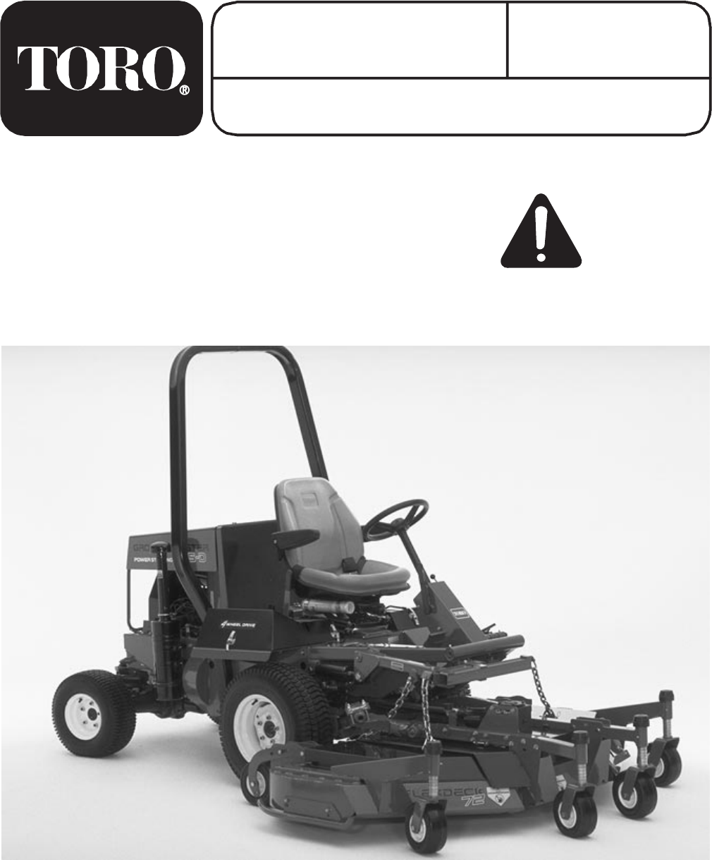
FORM NO. 3326 467 MODEL NO. 30799 - 210000001 & UP OPERATOR'S MANUAL 72 Flex Deck Side Discharge Mower FOR GROUNDSMASTER 300 SERIES TRACTION UNITS To ensure maximum safety, optimum performance, and to gain knowledge of the product, it is essential that you or any other operator of the machine read and understand the contents of this manual before the engine is ever started.
FOREWORD The 72" Flex Deck Side Discharge Mower has advanced concepts in engineering, design and safety; and if maintained properly, will give excellent service. Since this is a high-quality product, Toro is concerned about the future use of the machine and safety of the user. Therefore, read this manual to familiarize yourself with proper set-up, operation and maintenance instructions. The major sections of the manual are: 1. Safety Instructions 2. Setup Instructions 3. Before Operating 4. Operation 5.
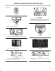
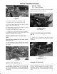
SAFETY AND INSTRUCTION DECALS The following decals are installed on the machine. If any become damaged or illegible, replace it. The decal part number is listed below and in your parts catalog. Replacements can be ordered from your Authorized Toro Distributor. 93-3709 104-2526 1. Warning—read the operator’s manual. 2. Lower cutting unit before going down hills. When operating the Groundsmaster 325-D or 345 two-wheel drive or four-wheel drive, rear weight must be added to the machine. 100-6582 1.
SAFETY AND INSTRUCTION DECALS 93-6697 1. Change the gearbox oil every 50 hours. Read the operator’s manual for further instructions. 104-7449 1. Height-of-cut setting for rear castor wheels on right chamber 92-3035 93-7824 1. Thrown object hazard—keep bystanders away. 2. Thrown object hazard from mower—keep the deflector in place. 3. Cutting/dismemberment hazard of hands or feet—stay away from rotating blades and moving parts. 1. Height-of-cut setting for front castor wheels. 100-8039 1.
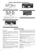
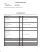
SPECIFICATIONS Options: High Lift Blade: Height of cut spacers 1/4″ Foam Filled 8″ Tire Part No. 23 2410 Part No. 54 8810 Part No. 93 5974 Specifications and design subject to change without notice. LOOSE PARTS NOTE: Use this chart as a checklist to ensure that all parts have been received. Without these parts, total set-up cannot be completed. Description Qty. Use Hose clamp 1 Hose bracket 2 Capscrew, 1/4 x 1 in. 2 Nut 2 Push arm adapter 1 Push arm plate 1 Capscrew, 3/8 x 2-3/4 in.
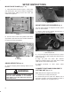
SETUP INSTRUCTIONS MOUNT HOSE CLAMP (Fig. 1 -2) 1. Using dimensions shown in figure 1, locate, mark and drill (2) .28 in. dia. holes in traction unit platform. Use caution when drilling as there are hoses and cables under platform. 4.41" 1 Figure 3 1. grass Deflector MOUNT REAR CASTOR WHEELS (Fig. 4) .75" 12.75" The rear castor wheels are shipped secured upside down to deck brackets. 1. Remove capscrew and locknut securing front of rear castor pivot to deck bracket. Figure 1 2.
SETUP INSTRUCTIONS WARNING 2 Since the right hand push arm is spring loaded to about 100 pounds, a helper is needed to push the arm down. Sudden release of the push arm could cause injury. 1 7. Have a helper carefully push down on the right push arm until holes in ball joint mount line up with holes in castor arm. Immediately slide a 4 x 4 in. block of wood between top of push arm and underside of chassis. 2 3/8 in. 3 Figure 5 1. Ball joint 2. Jam nut 3. Push arm adapter 8.
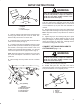
SETUP INSTRUCTIONS 3. Remove 2 flange head capscrews and flange nuts securing left hand ball joint mount to castor arm. Remove ball joint mount from castor arm. 4. Install ball joint to left hand ball joint mount with a castle nut and cotter pin. MOUNT FRONT LIFT ARM (Fig. 10 & 11) 1. Remove rubber bumper from bottom of traction T bar. 1 1 2 3 2 Figure 10 1. Traction T bar 2. Rubber bumper Figure 8 1. L.H. Push Arm 2. Ball joint 3. Ball Joint Mount 5.
SETUP INSTRUCTIONS 2 Front Left - 8th link Front Right - 8th link Rear - 14th link (All links) Check operation to ensure that all chains lift deck tight against stops when lift arm is raised. 1 1 Figure 13 1. Lift bracket 2. Castor arm 3 2 2. Hook H.O.C. chain onto remaining U bolt. 3. Thread a hex nut onto each end of U bolt. 4. Loosely mount U bolt and H.O.C. chain to rear lift bracket 2 nuts and 2 flange nuts Figure 15 5. Mount height of cut chain to 2 in.
SET-UP INSTRUCTIONS INSTALL REAR WEIGHT GROUNDSMASTER 300 Series Traction Units comply with ANSI B71.4-1999 Standard when equipped with rear weight. Use chart below to determine combinations of weight required. Order parts from your local Authorized Toro Distributor. Traction Unit Description Rear Weight Required Weight Part Number Weight Description Qty. Groundsmaster 325 D (30788/30739*) 210 lb. 24 5780 Rear Weight Kit (includes two 35 lb.
BEFORE OPERATING ADJUSTING HEIGHT OF CUT REAR CASTOR WHEELS The height of cut is adjustable from 1 to 4 inches in 1/4 inch increments. 1. Start the engine and raise the cutting unit so height of cut can be changed. Stop engine after cutting unit is raised. Figure 20 FRONT CASTOR WHEELS 1. Remove hairpin cotter and cotter pin securing rear castor pivot arm to deck bracket. Figure 18 1 1. Remove H.O.C. cap from spindle shaft and slide spindle out of front castor arm.
BEFORE OPERATING ADJUST ROLLERS The front anti scalp rollers and the rear anti scalp rollers, located on the center deck, should be located in upper holes for 1 and 1 1/2 inch heights of cut and lower holes for 2 to 5 inch heights of cut. Six rollers are located on the deck, two under the main deck and two on each wing. Figure 23 CHECK TIRE PRESSURE Ensure that the air pressure in the front and rear castor wheels is 40 psi (276 kPa).
OPERATING INSTRUCTIONS GRASS DEFLECTOR (Fig. 26) WARNING OPERATING TIPS 1. MOW WHEN GRASS IS DRY-Mow either in the late morning to avoid the dew, which causes grass clumping or in late afternoon to avoid the damage that can be caused by direct sunlight on the sensitive, freshly mowed grass. The grass deflector (Fig. 26) is a safety device that diverts grass and other foreign objects being discharged downward.
LUBRICATION GREASING THE CUTTING UNIT The cutting unit must be lubricated regularly. If machine is operated under normal conditions, lubricate castor bearings and bushings with No. 2 general purpose lithium base grease or molybdenum base grease, after every 8 hours of operation or daily, whichever comes first. 1. The cutting unit has bearings and bushings that must be lubricated, and these lubrication points are: front castor spindle bushings (2) (Fig. 27); front castor wheel bearings (4) (Fig.
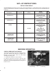
85 To 110 MAINTENANCE TROUBLE SHOOTING 15
MAINTENANCE CAUTION To prevent accidental starting of the engine, while performing maintenance, shut engine off and remove key from ignition switch. SEPARATING CUTTING UNIT FROM TRACTION UNIT 1. Position machine on level surface, lower cutting unit to floor, shut engine off and engage parking brake. 2. Remove self tapping screws securing shield to top of cutting unit and set shield aside. 3. Drive out roll pin securing drive shaft yoke to input shaft of gear box.
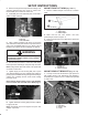
MAINTENANCE SERVICING FRONT BUSHINGS IN CASTOR ARMS The castor arms have bushings pressed into the top and bottom of the tube and after many hours of operation, the bushings will wear. To check the bushings, move castor fork back and forth and from side to side. If castor spindle is loose inside the bushings, bushings are worn and must be replaced. 1 Figure 33 1. Spring tensioning rod (3) REPLACING DRIVE BELTS The blade drive belts, tensioned by the spring loaded idlers, are very durable.
MAINTENANCE 1. Remove locknut from capscrew holding castor wheel assembly between castor fork. Grasp castor wheel and slide capscrew out of fork. 2. Pull spanner bushing out of wheel hub. 2. Remove two capscrews, locknuts, and springs securing deflector mounts to pivot brackets. 3. To remove the pivot brackets, remove carriage bolts and nuts. 4. Reinstall pivot brackets on top of discharge opening with carriage bolts and nuts. Head of carriage bolts must be on inside of cutting unit. 5.
MAINTENANCE 3 2 1 Figure 38 1. Blade bolt 2. Lockwasher 3. Anti-Scalp Cup Figure 39 DANGER 2. Install blade sail facing toward cutting unit with anti scalp cup, lock washer, and blade bolt. Tighten blade bolt to 85-110 ft. lb. WARNING Do not try to straighten a blade that is bent, and never weld a broken or cracked blade. Always use a new blade to ensure continued safety certification of the product. INSPECTING AND SHARPENING BLADE 1.
MAINTENANCE CORRECTING CUTTING UNIT MISMATCH If there is mismatch between the blades, the grass will appear streaked when it is cut. This problem can be corrected by making sure the blades are straight and all blades are cutting on the same plane. 1. Using a 3 foot long carpenters level, find a level surface on the shop floor. 2. Raise height of cut to the highest position: refer to Adjusting Height of Cut. 3. Lower cutting unit onto flat surface. Remove covers from top of cutting unit. 4.