Form No. 3327–739 72” Flex Deck Side Discharge Mower Model No.
Warning Before Operating . . . . . . . . . . . . . . . . . . . . . . . . . . . . Check Lubricant In Gear Box . . . . . . . . . . . . . . . . Adjusting Height-of-cut . . . . . . . . . . . . . . . . . . . . Check Tire Pressure . . . . . . . . . . . . . . . . . . . . . . . Adjust Skid . . . . . . . . . . . . . . . . . . . . . . . . . . . . . . Adjust Rollers . . . . . . . . . . . . . . . . . . . . . . . . . . . . Operation . . . . . . . . . . . . . . . . . . . . . . . . . . . . . . . . . . Grass Deflector . .
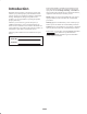
This manual identifies potential hazards and has special safety messages that help you and others avoid personal injury and even death. Danger, Warning, and Caution are signal words used to identify the level of hazard. However, regardless of the hazard, be extremely careful. Introduction Read this manual carefully to learn how to operate and maintain your product properly. The information in this manual can help you and others avoid injury and product damage.
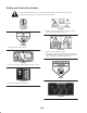
Safety and Instruction Decals Safety decals and instructions are easily visible to the operator and are located near any area of potential danger. Replace any decal that is damaged or lost. 93-3709 93-7818 1. Warning—torque the blade bolt to 115–149 N⋅m. Read the operator’s manual for further instructions. 100-6582 1. Warning—Cutting hazard of hands 104-2526 1. Warning—read the operator’s manual. 2. Lower cutting unit before going down hills.
100-6578 100-8039 1. Entanglement hazard—keep belt covers in place. Stay away from moving parts. 1. Height-of-cut setting for rear castor wheels on left chamber 93-6697 1. Change the gearbox oil every 50 hours. Read the operator’s manual for further instructions. 104-7449 1. Height-of-cut setting for rear castor wheels on right chamber 93-7824 92-3035 1. Thrown object hazard—keep bystanders away. 2. Thrown object hazard from mower—keep the deflector in place. 3.
Specifications Note: Specifications and design subject to change without notice. General Specifications Configuration Three blades, one blade center section, and two 1 blade floating wings. Wings flex up and down 12 degrees in a single plane perpendicular to from center section. Height of Cut Adjustable front and rear, in .50 inch increments from 1 to 4 inches. Construction 12-gauge steel, 5.25 inches deep, welded construction and reinforced with 10-gauge steel channels. Blades Three 25 inch long, .
Setup Note: Determine the left and right sides of the machine from the normal operating position. Loose Parts Note: Use this chart as a checklist to ensure that all parts necessary for assembly have been received. Without these parts, total setup cannot be completed. Some parts may have already been assembled at the factory. Description Qty. Hose clamp 1 Hose bracket 2 Capscrew, 1/4 x 1 in. 2 Nut 2 Push arm adapter 1 Push arm plate 1 Capscrew, 3/8 x 2-3/4 in.
Setup Instructions Mount Hose Clamp 1. Using dimensions shown in figure 1, locate, mark and drill (2) .28 in. dia. holes in traction unit platform. Use caution when drilling as there are hoses and cables under platform. 1 4.41” Figure 3 1. Grass deflector Mount Rear Castor Wheels .75” The rear castor wheels are shipped secured upside down to deck brackets. 12.75” 1. Remove capscrew and locknut securing front of rear castor pivot to deck bracket. Figure 1 2.
2. Thread ball joint into push arm adapter until a dimension of 2-3/8 in. from end of adapter to center of ball joint is attained. Do not tighten jam nut. Warning Since the right hand push arm is spring loaded to about 100 pounds, a helper is needed to push the arm down. Sudden release of the push arm could cause injury. 2 1 3 8. Have a helper carefully push down on the right push arm until holes in ball joint mount line up with holes in castor arm. Immediately slide a 4 x 4 in.
Mount Front Lift Arm 3. Remove 2 flange head capscrews and flange nuts securing left-hand ball joint mount to castor arm. Remove ball joint mount from castor arm. 1. Remove rubber bumper from bottom of traction T-bar. 4. Install ball joint to left-hand ball joint mount with a castle nut and cotter pin. 1 1 2 2 3 Figure 9 1. Traction T–bar 2. Slide front lift arm onto traction unit t-bar, positioning as shown in Figure 10. Figure 8 1. L.H. Push arm 2. Ball joint 2. Rubber bumper 3.
1 1 3 2 Figure 13 1. Drive shaft Figure 11 1. Lift bracket 2. Square U–bolt 3. U–bolt Install Lift Chains 1. Connect lift chains to lift arm and cutting unit chain brackets with (6) shackles, (3/8 x 1-1/2 in.) shackle pins and (1/8 x 3/4 in.) cotter pins. To ensure that cutting unit lifts properly, secure chains to the following links when connecting: 2 • Front Left – 8th link • Front Right – 8th link • Rear – 14th link (All links) 1 2.
Adjust Counter Balance Spring 1. Tighten nuts on adjusting rod until there is equal weight on castor wheels of left and left center chambers. 1 2 Figure 15 1. Counterbalance spring 2. Adjusting rod Grease Cutting Unit Before the cutting unit is operated, it must be greased to ensure proper lubricating characteristics: refer to Lubrication, page 13. Failure to properly grease the cutting unit will result in premature failure of critical parts.
Front Castor Wheels Before Operating Check Lubricant In Gear Box The gear box in designed to operate on SAE 80–90 wt. gear lube. Although the gear box is shipped with lubricant from the factory, check the level before operating the cutting unit. 1. Position the machine and cutting unit on a level surface. Figure 17 1. Remove H.O.C. cap from spindle shaft and slide spindle out of front castor arm. Slide spacers onto spindle shaft to get desired height-of-cut. 2.
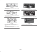
Rear Castor Wheels Figure 19 1. Remove hairpin cotter and cotter pin securing rear castor pivot arm to deck bracket. 1 Figure 21 1. H.O.C chain 1 Figure 20 1. Rear castor pivot 2. Align the pivot arm holes with selected height-of-cut bracket holes in the deck frame, install cotter pin and secure with hairpin cotter. Figure Rear Deck Chain 22 Check Tire Pressure 1. Remove hair pin cotter and clevis pin securing height-of-cut chain to chamber bracket.
Adjust Skid Skid, on right side of cutting unit, should be located in upper holes for 1 and 1-1/2 inch heights-of-cut and lower holes for 2 to 4 inch heights-of-cut. 1. Adjust skid by removing flange nuts, positioning as desired and re-installing flange nuts. 1 Figure 24 1 1. Roller Figure 23 1.
• SELECT THE PROPER HEIGHT–OF–CUT SETTING TO SUIT CONDITIONS – Remove approximately one inch or no more than 1/3 of the grass blade when cutting. In exceptionally lush and dense grass you may have to raise your height–of–cut setting another notch. When cutting in 1 in. or 1-1/2 in. height-of-cut, add a second washer between rear castor forks and bottom of castor arm housings to increase blade rake.
Maintenance Greasing The Cutting Unit The cutting unit must be lubricated regularly. If machine is operated under normal conditions, lubricate castor bearings and bushings with No. 2 general purpose lithium base grease or molybdenum base grease, after every 8 hours of operation or daily, whichever comes first. Figure 28 1. The cutting unit has bearings and bushings that must be lubricated, and these lubrication points are: front castor spindle bushings (2) (Fig. 26); front castor wheel bearings (4) (Fig.
85 T o 110 Trouble Shooting 18
Separating Cutting Unit From Traction Unit Mounting Cutting Unit To Traction Unit 1. Position machine on level surface, lower cutting unit to floor, shut engine off and engage parking brake. 1. Position machine on a level surface and shut engine off. 2. Move cutting unit into position in front of traction unit. 2. Remove self tapping screws securing shield to top of cutting unit and set shield aside. Warning 3. Drive out roll pin securing drive shaft yoke to input shaft of gear box.
MAINTENANCE Servicing Front Bushings In Castor Arms The castor arms have bushings pressed into the top and bottom of the tube and after many hours of operation, the bushings will wear. To check the bushings, move castor fork back and forth and from side to side. If castor spindle is loose inside the bushings, bushings are worn and must be replaced. 1 1. Raise cutting unit so wheels are off floor and block it so it cannot fall accidentally. Figure 32 2.
Servicing Castor Wheels And Bearings Replacing Grass Deflector 1. Position machine on a level surface, raise cutting unit, engage parking brake, be sure traction pedal is in neutral position, PTO lever in OFF position, shut engine OFF, and remove key from switch. Block cutting unit to prevent it from falling accidentally. The castor wheel rotates on a high-quality roller bearing and is supported by a spanner bushing.
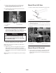
3 2 1 Figure 37 1. Blade bolt 2. Lockwasher 3. Anti–scalp cup Figure 38 3. Inspect cutting edges of all blades. Sharpen the cutting edges if they are dull or nicked. Sharpen only the top of the cutting edge and maintain the original cutting angle to make sure of sharpness (Fig. 39). The blade will remain balanced if same amount of metal is removed from both cutting edges. 3. Install blade—sail facing toward cutting unit with anti-scalp cup, lock washer, and blade bolt. Tighten blade bolt to 85–110 ft.
Correcting Cutting Unit Mismatch 6. Compare measurements of outer blades with the center blade. Center blade must not be more than 3/8 of an inch lower than the outer blades. If center blade is more than 3/8 of an inch lower than the outer blades. proceed to step 7 and add shims between spindle housing and bottom of cutting unit. If there is mismatch between the blades, the grass will appear streaked when it is cut.
The Toro General Commercial Products Warranty A Two-Year Limited Warranty Conditions and Products Covered The Toro Company and its affiliate, Toro Warranty Company, pursuant to an agreement between them, jointly warrant your 1996 or newer Toro Commercial Product (“Product”) purchased after January 1, 1997, to be free from defects in materials or workmanship for two years or 1500 operational hours*, whichever occurs first.