Form No.
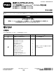
手順 3 4 5 6 7 8 数量 内容 リンクマウント ボルト3/8 x 1インチ ナット(3/8 インチ 昇降アームアセンブリ ボルト7/8 x 4-1/2 インチ ジャムナット7/8 インチ スピンドルワッシャ ボルト1/2 x 1-1/2 インチ ロックナット1/2 インチ ピボットピン グリスフィッティング T字フィッティングモデル 30812 のみ ホースクランプ3/8 インチ ケーブルタイ リレーブラケット リレー ボルト1/4 x 1/2 インチ ナット(1/4 インチ ボルト1/4 x 3/4 インチ デカル補助電源ユニットキットから スイッチ リレーブラケット リレー ボルト1/4 x 1/2 インチ ナット(1/4 インチ ボルト3/8 x 2 インチ ワッシャ0.
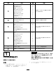
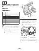
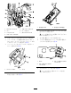
2 昇降アームアセンブリを取り付け る モ デ ル 30810 この作業に必要なパーツ 1 シリンダサポートアセンブリ 2 ボルト3/8 x 2-3/4 インチ 3 ボルト3/8 x 1-1/4 インチ 1 ボルト 3/8 x 1インチ 3 ナット(3/8 インチ 1 昇降アームアセンブリ 2 ボルト7/8 x 4-1/2 インチ 2 ジャムナット 7/8 インチ 8 スピンドルワッシャ 1 ボルト1/2 x 1-1/2 インチ 1 ロックナット 1/2 インチ 1 シリンダマウントのピボットピン 1 グリスフィッティング 図1 1. 2. ボルト 2.
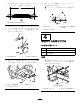
3. 昇降アームアセンブリを後フレーム部材に取 り付けるボルト7/8 x 4-1/2 インチ2 本、ジャム ナット7/8 インチ2個と、スピンドルワッシャ を必要なだけ使用して昇降アームと後フレー ム部材の左右を均等にする。 6. ねじ山付きリンクの端をシリンダサポートア センブリに固定する ボルト1/2 x 1-1/2 インチ1 本、ロックナット1/2 インチ1個を使用して図 5 のように取り付ける。 注 各コンポーネントは 図 3 のように組み付 ける。 図5 1. 昇降アダプタ 2. シリンダサポートアセンブリ 図3 1. ボルト7/8 x 4-1/2 インチ 3. スピンドルワッシャ 2. 昇降アームアセンブリ 4. ジャムナット 4. ボルトとロックナットを518648Nm5366kg.m = 382478ft-lbにトルク締めする。 5. ねじ山付きリンクの長さを 190mm にセットし てジャムナットを締めつける図 4。 7.
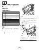
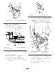
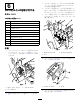
3 昇降アームアセンブリを取り付け る モ デ ル 30812 この作業に必要なパーツ 1 リンクマウント 3 ボルト 3/8 x 1インチ 3 ナット(3/8 インチ 1 昇降アームアセンブリ 2 ボルト7/8 x 4-1/2 インチ 2 ジャムナット 7/8 インチ 8 スピンドルワッシャ 1 ボルト1/2 x 1-1/2 インチ 1 ロックナット 1/2 インチ 1 ピボットピン 1 グリスフィッティング 図7 1. 2. リンクマウント 昇降アームアセンブリを後フレーム部材に取 り付けるボルト7/8 x 4-1/2 インチ2 本、ジャム ナット7/8 インチ2個と、スピンドルワッシャ を必要なだけ使用して昇降アームと後フレー ム部材の左右を均等にする。 注 各コンポーネントは 図 8 のように組み付 ける。 手順 注 キットの取り付け作業にあたり、機体後部を持ち 上げてジャッキスタンドで支え、右後タイヤを取り 外してください。 1.
4. ねじ山付きリンクの長さを 190mm にセットし てジャムナットを締めつける図 9。 ピボットピンの端部に、グリスフィッティン グを取り付ける図 11。 7. 注 フィッティングは 図 12 のように組み付け る。 図9 1. 5. ねじ山付きリンクの長さ—190mm 図 12 ねじ山付きリンクの端をリンクサポートアセ ンブリに固定する ボルト1/2 x 1-1/2 インチ1 本、ロックナット1/2 インチ1個を使用して図 10のように取り付ける。 1. ピボットピン 2. グリスフィッティング 3. グリスフィッティングの角度 — 45度 4 油圧ホースを取り付ける この作業に必要なパーツ 図 10 1. 6. ねじ山付きリンク 2. リンクサポートアセンブリ 1 T字フィッティングモデル 30812 のみ 3 ホースクランプ3/8 インチ 4 ケーブルタイ 手順 油圧シリンダの固定側をフレームのクロス部 材の下側に、ピボットピンで固定する図 11。 1.
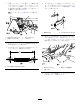
図 16 1. 図 14 モデル 30812 1. ラジエターフレーム 2. B. マニホルドからオイルクーラの戻りホースの 場所へ短いホースを配置する。 3. モ デ ル 30810 で は 、 以下の要領で短いホース をオイルクーラのホースに接続する 2. 字フィッティング ラジエターのフレームからおよそ127mm のところで戻りホースを切断する図 17。 注 これはデッキ昇降バルブとオイルクー ラをつなぐホース。油圧オイルをなるべ くこぼさないようにホースの両端を上向 きに持つ。 オイルクーラの戻りホース 2. A. 短いホース オイルクーラの戻りホースのハードライ ンからキャップを外す図 15。 図 15 1. 短いホース 2. ハードラインのキャップ 3. オイルクーラの戻りホース 図 17 4. B. ハードラインに短いホースをねじ込む図 15 。 C. ステップ 5へ進む。. 1. ここでホースを切断する。 3. デッキ昇降バルブへ 2. 字フィッティング 4.
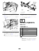
図 20 図 18 1. プラグ 2. ケーブルタイ 長いホース 1. 2. バルブアセンブリ 3. バルブ 6. バルブアセンブリの左側にあるプラグを外す 図 18 。 9. 長いホースをケーブルタイ4本で固定する図 20 。 7. バルブに油圧バルブフィッティングを取り付 ける 図 19 。 10. ホースのフィッティングをストレートフィッ ティングに固定する図 19。 5 リレーとスイッチを取り付ける モ デ ル 30810 この作業に必要なパーツ 図 19 1. 8. ホース 2. ストレートフィッティング 長いホースを、ラジエターフレームの下から クロス部材の上へ、そしてフレームのレール に沿ってバルブへ導く図 20。 注 長いホースは、トランスミッションベイか らバルブアセンブリに入るホースと並びます。 1 リレーブラケット 6 リレー 6 ボルト 1/4 x 1/2 インチ 7 ナット(1/4 インチ 1 ボルト 1/4 x 3/4 インチ 1 デカル補助電源ユニットキットから 2 スイッチ 手順 1.
図 23 図 21 1. 1. 2. ボルト1/4 x 1/2 インチ リレー 5. サポートチューブのナット 6. リレーブラケット 3. ナット(1/4 インチ 7. ボルト1/4 x 3/4 インチ 4. サポートチューブのボルト 6. 打ち抜きプラグ 2. 打ち抜きプラグの位置 パネルの打ち抜き穴を覆っているデカルを慎 重にはがして除去する。 注 スイッチ取り付けに必要なプラグとデカル のみに作業を行うこと。 2. サポートチューブからボルトとナットを外す。 7. 打ち抜き部分のバリなどを除去する。 3. リレーブラケットを機体に取り付けるボルト 1/4 x 3/4 インチとナット1/4 インチと、いま外 したボルトとナットを使用する図 21。 8. パネルの表面をきれいにして穴を取り囲むよ うにデカルを貼り付ける図 24。 4. コントロールパネルカバーのラッチを外して カバーを取り外す図 22。 図 24 1. デカル 2. フロート/押圧スイッチ2ポジ ションスイッチ 図 22 1. 5. コントロールパネル 2. 9.
6 リレーとスイッチを取り付ける モ デ ル 30812 3. ブラケットを外して、ドリルで穴7mmを開け る。マークの下は二重壁になっているので、 その両方を貫通させる。 4. ブラケットを仮止めしていた金具を使用して 新しい穴にブラケットを取り付けるボルト1/4 x 2-1/2 インチとナット1/4 インチを使用する。 5. リレー6個をブラケットに取り付けるボルト 1/4 x 1/2 インチ6本とロックナット1/4 インチ6 個を使用する。 この作業に必要なパーツ 1 リレーブラケット 6 リレー 6 ボルト 1/4 x 1/2 インチ 7 ナット(1/4 インチ 1 ボルト 3/8 x 2 インチ 1 ワッシャ 0.406 inch 1 ナット(3/8 インチ 6 ボルト 1/4 x 1/2 インチ 6 ロックナット 1/4 インチ 1 デカル補助電源ユニットキットから 2 スイッチ 手順 1. 図 26 フレームにリレーブラケットを仮止めするボ ルト3/8 x 2 インチ、ワッシャ0.
7 ワイヤハーネスを取付ける この作業に必要なパーツ ワイヤハーネス 1 手順 注 補助パワーユニットキット P/N 30382 が搭載され ている必要があります。 図 28 1. 8. 打ち抜きプラグ 2. 1. ワイヤハーネスの配設作業中にコネクタがほ こりなどで汚れないように、ワイヤハーネス から出ているコネクタをマスキンテープなど で保護する。 2. ワイヤハーネス図 30と 図 31を以下の場所に 取り付ける 打ち抜きプラグの位置 コントロールパネルの打ち抜き部を覆っている デカルを慎重に切り取って穴を露出させる。 注 スイッチ取り付けに必要なプラグとデカル のみに作業を行うこと。 9. 10.
図 30 図 31 1. ブロア PTO スイッチブロア用 6. デッキ昇降アウト AとB 2. 3. 昇降スイッチ アース 7. メインのワイヤハーネス 8. リレー 6個 4. 電源 5. デッキ昇降イン AとB 9. 10.
運転操作 8 昇降スイッチ 取り付けを完了する 必要なパーツはありません。 昇降スイッチを上昇位置にするとアタッチメントが 上昇し、下降位置にするとアタッチメントが下降 します 図 33 。 手順 押圧 ス イ ッ チ フ ロ ー ト /押 1. 新しいグリス注入部すべてにNo.2汎用リチウ ム系グリスを注入する。 2. 油圧オイルの量を点検し、必要に応じて補給 する。 3. バッテリーのマイナス-ケーブルを接続する。 4. エンジンを始動して後部昇降装置の試運転を 行う。オイル漏れがないか点検し、必要に応 じてオイルを補給する。 スイッチをフロート位置にするとアタッチメント がアンジュレーションに沿って滑らかに上下しま す。スイッチを押圧位置にすると、アタッチメン トを地面に押し付けて作業をすることができます 図 33。押圧を強くすると、その分だけ走行力がち いさくなります。 注 正しく組み付けられていれば、キーが OFF 位置にあるときにはマニホルドに通電されま せん。 図 32 モデル 30810 1. フロート/押圧スイッチ 2.
4. エンジンをアイドル回転させた状態で後部ア タッチメントを上昇させ、フードに接触しな いことを確認する。 図 34 1.
モ デ ル 30810 用 ウ ェ イ ト 一 覧 表 必要な前ウェイトの種類や数については次の表で確認してください。 刈 幅 72 イ ン チ モ デ ル 30695 に 30354 、 30481 、 ま た は 30353 お よ び 後部 QASモデル 30810搭載でアタッチメントなし 仕上げグレーダボックスレーキ モデル 08754 スチール製ドラグマット モデル 08757 ツースレーキ モデル 08751 ツースレーキスプリングレーキ モデル 08752 ココナツマット モデル 08758 ネイルドラッグ モデル 08781 ブロア モデル 30393 必要となる前ウェイト ウェイトのパーツ番号 ウェイトの名称 数量.
スチール製ドラグマット モデル 08757 238 kg 125-2655-03 、 125-2670 、 および 114-4096 前フレーム 用ウェイト、 ウェイトブラケット、 およびスーツケー ス形ウェイト 4 1 3 ツースレーキ モデル 08751 211 kg 125-2655-03 、 125-2670 、 および 114-4096 前フレーム 用ウェイト、 ウェイトブラケット、 およびスーツケー ス形ウェイト 4 1 2 ツースレーキスプリングレーキ モデル 08752 238 kg 125-2655-03 、 125-2670 、 および 114-4096 前フレーム 用ウェイト、 ウェイトブラケット、 およびスーツケー ス形ウェイト 4 1 3 ココナツマット モデル 08758 238 kg 125-2655-03 、 125-2670 、 および 114-4096 前フレーム 用ウェイト、 ウェイトブラケット、 およびスーツケー ス形ウェイト 4 1 3 ネイルドラッグ モデル 08781 238 kg 125-2655-03 、 125-2
ココナツマット モデル 08758 252 kg 125-2655-03 、 125-2670 、 および 114-4096 前フレーム 用ウェイト、 ウェイトブラケット、 およびスーツケー ス形ウェイト 4 1 3 ネイルドラッグ モデル 08781 252 kg 125-2655-03 、 125-2670 、 および 114-4096 前フレーム 用ウェイト、 ウェイトブラケット、 およびスーツケー ス形ウェイト 4 1 3 ブロア モデル 30393 276 kg 125-2655-03 、 125-2670 、 および 114-4096 前フレーム 用ウェイト、 ウェイトブラケット、 およびスーツケー ス形ウェイト 4 1 4 非承認製品 ラーン社製グルーマ 提携メーカー製品 刈 幅 60 ま た は 62 イ ン チ モ デ ル 30362 と 30365 に ハ ー ド キ ャ ノ ピ モ デ ル 30359 お よ び 必要となる前ウェイト ウェイトのパーツ番号 ウェイトの名称 数 量.
モ デ ル 30812 用 ウ ェ イ ト 一 覧 表 必要な前ウェイトの種類や数については次の表で確認してください。 刈 幅 72 イ ン チ 、 モ デ ル 30495 ま た は 30487 に 30354、 30481 、 ま た は 30353 を 搭 載 し 、 ハ ー ド キ ャ ノ ピ モ デ ル 30349 は 搭 載 せ ず 、 必要となる前ウェイト ウェイトのパーツ番号 ウェイトの名称 数量.
刈 幅 62 イ ン チ モ デ ル 30495 ま た は 30487 に 30456 、 ま た は 30457 を 搭 載 し 、 ハ ー ド キ ャ ノ ピ モ デ ル 30349 は 搭 載 せ ず 、 必要となる前ウェイト ウェイトのパーツ番号 ウェイトの名称 数量.
ブロア モデル 30393 193 kg 非承認製品 ラーン社製グルーマ 提携メーカー製品 ヒント • 本機をご使用になる前に必ずこの オペレーター ズマニュアル をお読みになり内容をよく理解 してください • 後部アタッチメントに対応する適切なウェイト ブラケットおよびウェイトを車両前部に必ず 取り付けてください。 • 刈り込みを行う時は、後部アタッチメントと車 両前部の着脱タイプのウェイトをすべて外し てください。 • 後部アタッチメントは車幅よりも広いものが多 くあり、立木や建造物等にアタッチメントをぶ つける可能性がありますから、十分注意して作 業を行ってください。 • 周囲に人のいる場所では絶対に作業をしない でください。 保守 • 毎週または洗車直後に必ずNo.
メモ 21
メモ 22
米国外のディストリビュータ一覧表 国 電話番号 36 27 539 640 852 2155 2163 82 32 551 2076 ディストリビュータ 輸入販売代理 店 Maquiver S.A. Maruyama Mfg. Co. Inc. Mountfield a.s. コロンビア 日本 チェコ共和国 プエルトリコ 787 788 8383 Mountfield a.s. スロバキア Ceres S.A. コスタリカ 506 239 1138 Munditol S.A. アルゼンチン CSSC Turf Equipment (pvt) Ltd. Cyril Johnston & Co. Cyril Johnston & Co.
Toro 一 般 業 務 用 機 器 の 品 質 保 証 年間品質保証 保証条件および保証製品 Toro 社およびその関連会社であるToro ワランティー社は、両社の合意に基 づき、Toro 社の製品「製品」と呼びますの材質上または製造上の欠陥に対 して、2年間または1500運転時間のうちいずれか早く到達した時点までの品 質保証を共同で実施いたします。この保証はエアレータを除くすべての製品 に適用されますエアレータに関する保証については該当製品の保証書をご覧 下さい。 この品質保証の対象となった場合には、弊社は無料で「製品」 の修理を行います。この無償修理には、診断、作業工賃、部品代、運賃 が含まれます。保証は「製品」が納品された時点から有効となります。 *アワーメータを装備している機器に対して適用します。 保証請求の手続き 保証修理が必要だと思われた場合には、「製品」を納入した弊社代理店 ディストリビュータ又はディーラー に対して、お客様から連絡をして頂くことが 必要です。連絡先がわからなかったり、保証内容や条件について疑問があ る場合には、本社に直接お問い合わせください。 Toro Commercia