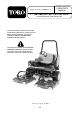
FORM NO. 3325-250 Rev A MODEL NO. 30822—200000001 & UP ® OPERATOR'S MANUAL 27" (68.5 mm) ROTARY CUTTING DECK For Groundsmaster® 3500 Traction Unit To understand this product, and for safety and optimum performance, read this manual before starting operation. Pay special attention to SAFETY INSTRUCTIONS highlighted by this symbol— The safety alert symbol means CAUTION, WARNING or DANGER—personal safety instruction. Failure to comply with the instruction may result in personal injury.
Contents Forward Contents 2 Forward 2 Safety 3 Specifications 6 Before Operating Adjust The Carrier Frame Adjust Height Of Cut Adjust The Roller Scraper Install The Mulching Baffle (Optional) 7 7 7 8 8 Operating Operating Tips 10 10 Maintenance Lubrication Cutting Deck Service Latch Separating the Cutting Decks from the Traction Unit Mounting the Cutting Decks to the Traction Unit Blade Plane Inspecting the Blade Plane Adjusting the Blade Plane Removing the Cutter Blade Inspecting and Sharpeni
Safety The Groundsmaster 3500-D was tested and certified by TORO for compliance with the B71.4-1999 specifications of the American National Standards Institute. Although hazard control and accident prevention partially are dependent upon the design and configuration of the machine, these factors are also dependent upon the awareness, concern, and proper training of the personnel involved in the operation, transport, maintenance, and storage of the machine.
Safety the recommended maximum limit of 25 degrees. are hazardous and could be deadly. 14. Sit on the seat when starting and operating the machine. Stay alert for holes in terrain and other hidden hazards which can cause a sudden change in side hill angle. Use extreme caution when operating close to sand traps, ditches, creeks, steep hillsides or other hazards. Reduce speed when making sharp turns. Do not turn on hills. Avoid sudden stops and starts. Use reverse pedal for braking.
Safety clothing, and any other parts of the body away from the cutting units and any moving parts. Keep everyone away. blades to stop spinning. D. Stop the engine and remove key from the ignition switch. 37. Do not overspeed the engine by changing governor settings. To assure safety and accuracy, have an Authorized Toro Distributor check maximum engine speed with a tachometer. 27. Whenever machine is left unattended, make sure, key is removed from ignition switch and parking brake is set.
Specifications Blade: Heat-treated steel. Roller footprint Front to back 29.3 inch (74.4 cm) Rear Roller 29.8 inch (75.7 cm) full length Front Rollers 18.5 inch (47.0 cm) between front rollers Tip Speed: 16,300 ft./min. nominal. Suspension: Non steering carrier frame. Blade Plane: (Factory pre-set) Height of Cut 2.00 (5.08 cm) Right or left side 2.15 (5.46 cm) Side to side Within 0.08 cm) of each other Blade rake Approximately 5/16 in. (0.79 cm) Weight: Height of Cut: 3/4–4 inches (1.91–10.
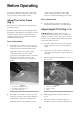
Before Operating clearance due to the higher position of the cutting chamber, but will cause the cutting decks to reach their maximum up travel sooner. To prevent accidental starting of the engine, while performing maintenance, shut off the engine and remove the key from the ignition switch. Rear Cutting Decks Adjust The Carrier Frame (Fig. 1) 1. The front and rear cutting decks require different mounting positions. Adjust Height Of Cut (Fig.
Before Operating hole and slot. Height of Cut 3 1 Figure 3 2 6. Figure 4 Position the taped plate in line with the spacer. 7. Install the capscrew finger tight. 8. Repeat steps 4–7 for each side adjustment. 9. Tighten all three capscrews; to 30 ft-lb. (41 N•m). 1. Roller scraper 2. Locknut 3. Mounting bracket NOTE: Adjustments of more than 3.8cm may require temporary assembly to an intermediate height to prevent binding (e.g. changing from 3.2cm to 6.9cm height of cut).
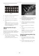
Before Operating Figure 5 1. Mulching baffle 3. Verify that the mulching baffle does not interfere with either the tip of the blade and does not protrude inside the surface of the rear chamber wall.
Operating 4. Operating Tips 1. 2. 3. MOW WHEN GRASS IS DRY—Mow either in the late morning to avoid the dew, which causes grass clumping, or in late afternoon to avoid the damage that can be caused by direct sunlight on the sensitive, freshly mowed grass. CHECK THE CONDITION OF THE DECK— Make sure the cutting chambers are in good condition. Straighten any bends in the chamber components to assure correct blade tip/chamber clearance.
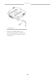
Maintenance Lubrication (Fig. 6) Each cutting deck has two grease fittings per spindle. Either fitting can be used, whichever is more accessible. If the machine is operated under normal conditions, lubricate the blade spindle bearings (Fig. 6) with No. 2 general purpose lithium base grease or molybdenum base grease, after every 50 hours of operation. Pump grease into the fitting until a small amount appears at bottom of the spindle housing (under the deck). 1 Figure 7 1. Service latch hook 5.
Maintenance sure the 0- ring in is position and not damaged. 5. Grease the spindle. Blade Plane The rotary deck comes from the factory preset at 5.1cm height of cut and blade rake of 0.70cm. The left and right hand heights are also preset to within ± 0.79mm of the other. 1 1 The cutting deck is designed to withstand blade impacts without deformation of the chamber. If a solid object is struck, inspect the blade for damage, and the blade plane for accuracy Figure 8 1. Motor mounting screws 3.
Maintenance 5. Rotate the marked end of the blade to the 3 and 9 o’clock positions and measure heights. 5. Verify 12 o’clock height and re-adjust if needed. 6. Compare 12 o’clock measured height to the height-of-cut setting. It should be within 0.76mm. The 3 and 9 o’clock heights should be 0.38 ± 0.76cm higher than the 12 o’clock setting and within 0.76cm of each other. 6. Determine if only one or both height-of-cut brackets need to be adjusted. If the 3 or 9 o’clock side is 0.38 ± 0.
Maintenance 2 1 1 3 1 Figure 12 1. Blade bolt 2. Cup 4 Figure 13 3. 1. 2. 3. 34 Install the blade sail facing toward the cutting deck with the cup and blade bolt. Tighten the blade bolt to (115-149 N•m). Do not try to straighten a blade that is bent, and never weld a broken or cracked blade. Always use a new blade to assure continued safety certification of the product. 3. Inspecting And Sharpening The Blade (Fig. 13–14) 1.
Maintenance Tighten the blade bolt to 115-149 N•m. 1 Blade Stopping Time The blades of the cutting deck should come to a complete stop in approximately 5 seconds after the cutting deck engagement switch is shut down. 4 NOTE: Make sure the decks are lowered onto a clean section of turf or hard surface to avoid thrown dust and debris. 2 5 3 To verify this stopping time, have a second person stand back at least six meters from the deck and watch the blades on one of the cutting decks.
Maintenance Figure 17 1. 2. 3. 4. 5. 4. Roller Roller shaft Ball bearing Retaining ring Oil seal 2. Install the spiral retaining ring on same end as the assembled bearing. 3. Install the shaft with a single bearing into the tube assembly. 4. Install the second bearing into the roller assembly. Press only on the inner race. The inner race will contact the shoulder of the shaft before the outer race contacts the shoulder of the housing. 5. Install the second spiral retaining ring. 6.
Maintenance components and re-assemble. Model and Serial Numbers Assembly The cutting deck has two identification numbers: a model number and a serial number. The two numbers are stamped into a plate on the rear of the mower deck, under the cover. In any correspondence concerning the mower, supply the model and serial numbers to assure that correct information and replacement parts are obtained. 1. Press the first bearing into the roller housing.