Form No. 3326-156 27 Rotary Cutting Deck Groundsmaster 3500 Traction Unit Model No.
Contents Introduction . . . . . . . . . . . . . . . . . . . . . . . . . . . . . . . . Safety . . . . . . . . . . . . . . . . . . . . . . . . . . . . . . . . . . . . . Safety and Instruction Decals . . . . . . . . . . . . . . . . Specifications . . . . . . . . . . . . . . . . . . . . . . . . . . . . . . . Optional Equipment . . . . . . . . . . . . . . . . . . . . . . . Dimensions . . . . . . . . . . . . . . . . . . . . . . . . . . . . . . General Specifications . . . . . . . . . . . . . . . . . . . . .
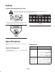
Safety Safety and Instruction Decals Safety decals and instructions are easily visible to the operator and are located near any area of potential danger. Replace any decal that is damaged or lost. 98-7818 1. Warning—torque the blade bolt to 85–110 ft.-lb (115–149 N⋅m). Read the operator’s manual for further instructions. 104-1086 43-8480 Specifications Dimensions Note: Specifications and design subject to change without notice.
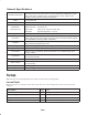
General Specifications Chamber Construction Blade Tip Speed Blade Plane (factory pre-set) Height of Cut Deck Drive Spindles Discharge Welded 10 GA (.1345 in.) and 12 GA (.1036 in.) steel. Spindle support is 3/16 in. high-strength steel and 10 GA exterior channels, withstands multiple blade impact tests. Deck frame is welded 1-1/2 in. square tubing and 7 GA (.1793 in.) side supports, protects chamber, withstands collisions. Heat treated steel 16,300 ft./min.
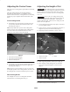
Adjusting the Carrier Frame Adjusting the Height of Cut The front and rear cutting decks require different mounting positions. Important This cutting deck often cuts approximately 1/4 inch lower than a reel cutting unit with the same bench setting. It may be necessary to have these rotary cutting deck’s bench set 1/4 inch above that of reels cutting in the same area. The front cutting deck has two mounting positions depending on what height-of-cut and degree of deck rotation is desired.
7. Install capscrew finger tight. 8. Repeat steps 4–7 for each side adjustment. 9. Tighten all three capscrews to 30 ft.-lb. (41 N⋅m). Note: Adjustments of more than 1-1/2 inch may require temporary assembly to an intermediate height to prevent binding (e.g. changing from 1.25 in. to 2.75 in. height-of-cut). Adjusting the Roller Scraper The rear roller scraper is designed to work best when there is an even gap of .02–.04 inches between the scraper and roller. 1 1.
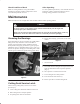
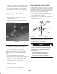
Check Condition of Deck After Operating Make sure cutting chambers are in good condition. Straighten any bends in chamber components to assure correct blade tip/chamber clearance. To ensure optimum performance, clean underside of mower housing. If residue is allowed to build up in mower housing, cutting performance will decrease. Maintenance Note: Determine the left and right sides of the machine from the normal operating position.
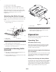
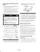
Separating the Cutting Decks from the Traction Unit Mounting the Cutting Decks to the Traction Unit 1. Position machine on level surface, lower cutting decks to floor, shut engine off, and engage parking brake. 1. Position machine on a level surface and shut engine off. 2. Move cutting deck into position in front of traction unit. 2. Disconnect and remove hydraulic motor from deck (Fig. 8). Cover top of spindle to prevent contamination. 3. Slide deck carrier frame onto lift arm pivot pin.
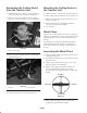
Removing the Cutter Blade 6. Compare 12 o’clock measured height to the height of cut setting. It should be within .03 inch. The 3 and 9 o’clock heights should be .15±.03 inch higher than the 12 o’clock setting and within .03 in. of each other. The blade must be replaced if a solid object is hit, the blade is out of balance or if the blade is bent. Always use genuine Toro replacement blades to be sure of safety and optimum performance.
Inspecting and Sharpening the Blade to make sure of sharpness (Fig. 14). The blade will remain balanced if same amount of metal is removed from both cutting edges. 1. Raise cutting deck to highest position, shut the engine off, and engage the parking brake. Block cutting deck to prevent it from falling accidentally. SHARPEN AT THIS ANGLE ONLY 2. Examine cutting ends of the blade carefully, especially where the flat and curved parts of the blade meet (Fig. 13-A).
3. Remove the lower screws securing each end of roller to roller mounts (Fig. 15). 1 2 1 2 3 4 4 5 3 Figure 17 m–5417 1. Roller 2. Roller shaft 3. Ball bearing Figure 15 1. Rear roller 2. Scraper 3. Roller mount 4. Lower screw 4. Retaining ring 5. Oil seal 5. Alternate tightening sequence of 1/4 in. capscrews to pull seal out of housing. Seal Removal Note: Seal will be destroyed when servicing the rear roller. Do not attempt to re-use these seals. Using a 1/4 in. thick, 3 in. x 3 in.
Servicing the Front Roller Cutting Deck Storage Disassembly If cutting deck is separated from traction unit for any length of time, install spindle plug (94-2703) in top of spindle to protect spindle from dust and water. 1. Remove roller mounting bolt (Fig. 18). 2. Insert punch through end of roller housing and drive opposite bearing out by alternating taps to opposite side of inner bearing race. There should be a 1/16 in. (.06 in.) lip of inner race exposed. 3 2 4 1 Figure 18 1. Front roller 2.