Form No. 3363-169 Rev B Debris Blower Groundsmaster® 200/3280-D/3320 Series Traction Unit Model No. 30823—Serial No. 310000001 and Up To register your product or download an Operator's Manual or Parts Catalog at no charge, go to www.Toro.com.
Contents Introduction Introduction................................................................. 2 Safety ........................................................................... 3 Before Operating ................................................. 3 While Operating................................................... 3 Maintenance......................................................... 3 Safety and Instructional Decals ............................. 4 Setup .............................................
Safety • Using the machine demands attention. To prevent loss of control: – Operate only in daylight or when there is good artificial light. – Drive slowly and watch for holes or other hidden hazards. – Do not drive close to a sand trap, ditch, creek, or other hazard. – Reduce your speed when making sharp turns and when turning on hillsides. – Avoid sudden starts and stops. – Before backing up, look to the rear and ensure that no one is behind the machine.
Check the fan shaft bearing mounting bolts and nuts frequently to be sure that they are tightened to specification. • Make sure that all hydraulic line connectors are tight and all hydraulic hoses and lines are in good condition before applying pressure to the system. • Keep your body and hands away from pin hole leaks in hydraulic lines that eject high pressure hydraulic fluid. Use cardboard or paper to find hydraulic leaks. Hydraulic fluid escaping under pressure can penetrate skin and cause injury.
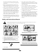
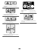
93-9083 1. Cutting/dismemberment hazard, fan—stay away from moving parts. 99-4487 1. Read the Operator's Manual. 2. Grease 3. Grease every 8 hours. 4. Grease every 100 hours. 93-6674 1. Crushing hazard, hand—read the instructions before servicing or performing maintenance. 105-0708 105-0698 1. Warning—thrown object hazard; keep bystanders away from machine. 1. Warning—read the Operator's Manual. 99-4486 1. Entanglement hazard, belt—stay away from moving parts, keep all guards and shields in place.
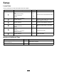
Setup Loose Parts Use the chart below to verify that all parts have been shipped. Procedure Description 1 2 3 4 5 6 Qty.
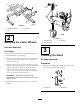
Note: Determine the left and right sides of the machine from the normal operating position. 1 Important: The fasteners on the covers of this machine are designed to remain on the cover after removal. Loosen all of the fasteners on each cover a few turns so that the cover is loose but still attached, then go back and loosen them until the cover comes free. This will prevent you from accidentally stripping the bolts free of the retainers.
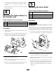
Figure 3 1. Attachment frame 3. Right arm 2. Stop 2 Figure 4 1. Tensioning cap Mounting the Castor Wheels 3. Spacers 2. Thrust washers No Parts Required 3 Procedure The castor wheel assemblies are installed upside down on the debris blower for shipping Lowering the Stand 1. Remove the tensioning caps from the spindle shafts and slide off the castor wheel, spacers, and thrust washers (Figure 4). No Parts Required Procedure 2. Slide the spacers onto the castor spindle to get the desired height.
2. Lower the stand. Install the pin through the upper set of holes in the stand and tube (Figure 5). Secure the pin. 5 3. Stand the blower up on the castor wheels and stand (storage position).
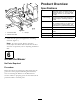
Product Overview Specifications Figure 8 1. End of the shaft 3. Roll pin Fan Backward curved, cast aluminum fan. 12 blades per side, 21 in. (53 cm) outside diameter, 6-3/8 in. (16 cm) width, 34 lb. (16 kg) Fan housing 10 gauge steel face plates welded to 10 gauge wrapper. Increasing scroll from cutoff. Fan drive PTO driven A 3VX banded belt drive to fan. Final drive ratio of 1.5:1 with a over running clutch in belt drive pulley. Fan shaft rotates on greaseable ball bearings.
Operation 3. Engage the PTO while the engine is at LOW IDLE. 4. Increase the engine speed to High IDLE. Transporting the Blower 5. Practice blowing material. It is advisable to blow the same direction the wind is blowing to prevent material from blowing back into the cleared area. 1. Reduce the engine speed to idle position. 2. Disengage the PTO and wait for the PTO to stop. 3. Raise the blower to the transport position.
Maintenance Lubrication Idler Arm Bearing The idler arm bearing (Figure 10) must be lubricated after every 8 hours of operation with a No. 2 Lithium-based grease. Figure 11 Lift Arm Pivots The (2) lift arm pivots (Figure 12) must be lubricated after every 8 hours of operation with a No. 2 Lithium based grease Figure 10 Overrunning Clutch Pulley The overrunning clutch pulley (Figure 10) must be lubricated after every 8 hours of operation with a No. 2 Lithium based grease.
2. A new belt is properly tensioned when the idler spring body is extended to a length of 3-1/4 to 3-1/2 in. (83-89 mm) (Figure 15). Figure 15 1. Idler spring 2. 3-1/4 to 3-1/2 in. (83-89 mm) 3. When the belt stretches, adjust it as follows: • Loosen the nut securing the belt tensioner to the blower housing. Figure 13 • Rotate the belt tensioner (Figure 15) until the idler spring body is extended to a length of 3-1/4 to 3-1/2 in. (83-89 mm) (Figure 16), then tighten the nut.
Storage 1. Lower the stand. Install the pin through the upper set of holes in the stand and tube (Figure 5). Secure the pin. 2. Stand the blower up on the castor wheels and stand. 3. Thoroughly clean the blower. The fan housing should be free of dirt, leaves, and debris. 4. Lubricate all grease fittings. Wipe off any excess lubricant. 5. Place a light coat of grease on the splines of the PTO adapter. 6. Tighten all fasteners.
Troubleshooting Problem The fan quits turning. There is excessive vibration. Possible Cause 1. Belt may be loose or broken. 1. Replace belt or adjust the tension of the belt. 2. Bearing pressed in the bearing mount may be damaged. 2. Replace the bearing, use #609 Loctite when replacing. 1. The bearing on the fan shaft is damaged. 1. Replace the bearings. 2. Material is built up on the fan blades. 2. Clean out any build up on the inside of the housing. 3. Reduce the PTO speed to 540 RPM. 3.
The Toro Total Coverage Guarantee A Limited Warranty Conditions and Products Covered The Toro Company and its affiliate, Toro Warranty Company, pursuant to an agreement between them, jointly warrant your Toro Commercial product (“Product”) to be free from defects in materials or workmanship for two years or 1500 operational hours*, whichever occurs first. This warranty is applicable to all products with the exception of Aerators (refer to separate warranty statements for these products).