Form No. 3393-444 Rev A Debris Blower Groundsmaster® 200/3280-D/3320 Series Traction Unit Model No. 30823—Serial No. 315000001 and Up Register at www.Toro.com.
Contents WARNING CALIFORNIA Proposition 65 Warning This product contains a chemical or chemicals known to the State of California to cause cancer, birth defects, or reproductive harm. Safety ........................................................................... 3 Before Operating .................................................... 3 While Operating...................................................... 3 Maintenance ...........................................................
Safety – Do not drive close to a sand trap, ditch, creek, or other hazard. Hazard control and accident prevention are dependent upon the awareness, concern, and proper training of the personnel involved in the operation, transport, maintenance, and storage of the machine. Improper use or maintenance of the machine can result in injury or death. To reduce the potential for injury or death, comply with the following safety instructions.
• • • be surgically removed within a few hours by a doctor familiar with this form of injury or gangrene may result. Before disconnecting or performing any work on the hydraulic system, all pressure in the system must be relieved by stopping the engine and lowering the blower to the ground. If the engine must be running to perform a maintenance adjustment, keep hands, feet, clothing, and other parts of the body away from the fan and other moving parts.
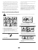
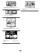
93-6674 1. Crushing hazard, hand—read the instructions before servicing or performing maintenance. 105-0708 1. Warning—thrown object hazard; keep bystanders away from machine. 105-0698 1. Warning—read the Operator's Manual. 99-4486 1. Entanglement hazard, belt—stay away from moving parts, keep all guards and shields in place. 99-4487 1. Read the Operator's Manual. 2. Grease 3. Grease every 8 hours. 4. Grease every 100 hours.
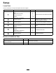
Setup Loose Parts Use the chart below to verify that all parts have been shipped. Procedure Description 1 2 3 4 5 6 Qty. Use Arm Stop Bolts (7/16 x 3 inches) Locknut (7/16 inch) Washer Bolt (7/16 x 3-1/4 inches) 2 1 4 6 12 2 Mount the arms to the attachment frame. No parts required – Mount the castor wheels to the debris blower (shipped on blower). No parts required – Lower the stand (shipped on blower).
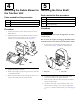
Note: Determine the left and right sides of the machine from the normal operating position. 1 Important: The fasteners on the covers of this machine are designed to remain on the cover after removal. Loosen all of the fasteners on each cover a few turns so that the cover is loose but still attached, then go back and loosen them until the cover comes free. This will prevent you from accidentally stripping the bolts free of the retainers.
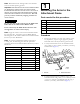
Figure 3 1. Attachment frame 3. Right arm 2. Stop 2 Figure 4 1. Tensioning cap Mounting the Castor Wheels 3. Spacers 2. Thrust washers No Parts Required 3 Procedure The castor wheel assemblies are installed upside down on the debris blower for shipping Lowering the Stand 1. Remove the tensioning caps from the spindle shafts and slide off the castor wheel, spacers, and thrust washers (Figure 4). No Parts Required Procedure 2. Slide the spacers onto the castor spindle to get the desired height.
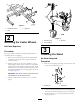
4 5 Mounting the Debris Blower to the Traction Unit Installing the Drive Shaft Parts needed for this procedure: Parts needed for this procedure: 1 Drive shaft 6 Bolts (7/16 x 3 inches) 1 Roll pin 6 Locknut (7/16 inch) 2 Bolt (5/16 x 1–1/2 inches) 12 Washer 2 Locknut (5/16 inch) Procedure Procedure 1. Position the traction unit in line with the rear of the debris blower. DANGER The PTO shaft rotates with enough force to cause serious injury. 2.
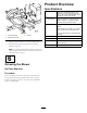
Product Overview Specifications Fan The fan is a backward curved, cast aluminum fan with 12 blades per side, 53 cm (21 inch) outside diameter, 16 cm (6-3/8 inch) width, 16 kg (34 lb). Fan housing The fan housing is 10 gauge steel face plates welded to a 10 gauge wrapper. Increasing the scroll from cutoff. Fan drive The PTO driven A 3VX banded belt drive to fan. The final drive has a ratio of 1.5:1 with a over running clutch in belt drive pulley. The fan shaft rotates on greaseable ball bearings.
Operation 5. Practice blowing material. Note: Blow the same direction the wind is blowing to prevent material from blowing back into the cleared area. Transporting the Blower 1. Reduce the engine speed to idle position. 2. Disengage the PTO and wait for the PTO to stop. 3. Raise the blower to the transport position. Adjusting the Discharge Opening The discharge opening is adjustable to increase or decrease air output velocity and volume. Decreasing the discharge opening size will increase the velocity.
Maintenance Recommended Maintenance Schedule(s) Maintenance Service Interval Maintenance Procedure After the first 20 hours • Make sure that the belt is properly tensioned to ensure proper operation of the machine and unnecessary wear. Before each use or daily • Check the blower belt. Every 20 hours • • • • • Lubricate the idler arm bearing every 20 hours or weekly. Lubricate the overrunning clutch pulley every 20 hours or weekly. Lubricate the 2 fan-shaft bearings every 20 hours or weekly.
Note: Check/adjust the blower belt tension after the first 20 hours of operation. 1. Loosen the 3 bolts and 3 nuts securing the belt guard to the blower housing (Figure 14), remove the guard. Note: The drive shaft does not have to be disconnected to adjust the belt. Figure 12 Drive Shaft and Guards Service Interval: Every 100 hours Every 20 hours Under normal conditions, grease the 2 drive shaft fittings after every 100 hours of use and the guards after every 8 hours of operation (Figure 13). Use a No.
Storage 1. Lower the stand. 2. Install the pin through the upper set of holes in the stand and tube (Figure 5). 3. Secure the pin. 4. Stand the blower up on the castor wheels and stand. 5. Thoroughly clean the blower. Note: The fan housing should be free of dirt, leaves, and debris. 6. Lubricate all grease fittings and wipe off any excess lubricant. Figure 16 1. Belt tensioner 7. Place a light coat of grease on the splines of the PTO adapter. 2. Belt-tensioner notch 8. Tighten all fasteners.
Troubleshooting Problem The fan quits turning. There is excessive vibration. There is lack of adequate air flow. Possible Cause Corrective Action 1. Belt may be loose or broken. 1. Replace belt or adjust the tension of the belt. 2. Bearing pressed in the bearing mount may be damaged. 2. Replace the bearing; use thread-locking compound when replacing. 1. The bearing on the fan shaft is damaged. 1. Replace the bearings. 2. Material is built up on the fan blades. 3.
Toro General Commercial Product Warranty A Two-Year Limited Warranty Conditions and Products Covered The Toro Company and its affiliate, Toro Warranty Company, pursuant to an agreement between them, jointly warrant your Toro Commercial product (“Product”) to be free from defects in materials or workmanship for two years or 1500 operational hours*, whichever occurs first. This warranty is applicable to all products with the exception of Aerators (refer to separate warranty statements for these products).