Form No. 3328–145 27 Rotary Cutting Deck Groundsmaster 3500, 4500/4700 Traction Unit Model No.
Contents Introduction . . . . . . . . . . . . . . . . . . . . . . . . . . . . . . . . . Safety . . . . . . . . . . . . . . . . . . . . . . . . . . . . . . . . . . . . . . Safety and Instruction Decals . . . . . . . . . . . . . . . . . Specifications . . . . . . . . . . . . . . . . . . . . . . . . . . . . . . . . General Specifications . . . . . . . . . . . . . . . . . . . . . Dimensions . . . . . . . . . . . . . . . . . . . . . . . . . . . . . . . Optional Equipment . . . . . . . . . . . . . . . . . . . . .
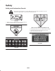
Safety Safety and Instruction Decals Safety decals and instructions are easily visible to the operator and are located near any area of potential danger. Replace any decal that is damaged or lost. 98-7818 1. Warning—torque the blade bolt to 85–110 ft.-lb (115–149 N⋅m). Read the operator’s manual for further instructions. 100-6583 (Affix over decal part no. 43–8480 for CE) 1. Thrown object hazard—stay a safe distance from the machine. 2.
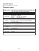
Specifications Note: Specifications and design subject to change without notice. General Specifications Chamber Construction Blade Tip Speed Blade Plane (factory pre-set) Height of Cut Deck Drive Spindles Discharge Welded 7 GA (.1793 in.),10 GA (.1345 in.) and 12 GA (.1036 in.) steel. Spindle support is 3/16 in. high-strength steel and 10 GA exterior channels, withstands multiple blade impact tests. Deck frame is welded 1-1/2 in. square tubing and 7 GA (.1793 in.
Dimensions Overall length 34 in. (86.4 cm) Overall width 34 in. (86.4 cm) Overall height 9.6 in. (24.4 cm) to carrier mount 10-1/2 in. (26.7 cm) at 3/4 in. height of cut 13-3/4 in. (34.9 cm) at 4 in. height of cut Roller footprint Front to back Rear roller Front rollers 29.5 in. (74.9 cm) 29.8 in. (75.7 cm) full length 18.5 in. (47 cm) between front rollers Optional Equipment Mulching Baffle Kit (contains parts for one deck) High Lift Blade Model No. 30828 Part No.
Setup Note: Determine the left and right sides of the machine from the normal operating position. Loose Parts Note: Use this chart as a checklist to ensure that all parts have been received. Without these parts, total setup cannot be completed. Description Qty. Use Decal 1 Apply to cutting deck for CE Parts Catalog 1 Operator’s Manual 1 Read before operating the machine. Registration Card 1 Fill out and return to Toro.
1. Loosen the top 2 mounting screws and the lower 2 flange nuts (Fig. 4). 2. Loosen capscrew securing each height of cut bracket to height of cut plate (front and each side) (Fig. 2). 3. Beginning with front adjustment, remove capscrew. 1 2 3 2 3 m–5417 Figure 4 1. Roller scraper 2. Mounting screw 1 3. Flange nut 2. Slide the scraper up or down until a gap of .020–.040 in. is achieved between the rod and the roller. Figure 2 1. Height of cut bracket 2. Height of cut plate 3.
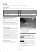
Mow When Grass is Dry Operation Mow either in the late morning to avoid the dew, which causes grass clumping, or in late afternoon to avoid the damage that can be caused by direct sunlight on the sensitive, freshly mowed grass. Note: Determine the left and right sides of the machine from the normal operating position. Operating Tips Select the Proper Height-of-Cut Setting to Suit Conditions Blade Selection Remove approximately one inch or no more than 1/3 of the grass blade when cutting.
Always Start Mowing with Sharp Blades A sharp blade cuts cleanly and without tearing or shredding the grass blades like a dull blade. Tearing and shredding causes the grass to turn brown at the edges which impairs growth and increases susceptibility to diseases. Make sure blade is in good condition and a full sail is present. Check Condition of Deck Make sure cutting chambers are in good condition. Straighten any bends in chamber components to assure correct blade tip/chamber clearance.
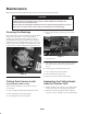
Maintenance Note: Determine the left and right sides of the machine from the normal operating position. Caution If you leave the key in the ignition switch, someone could accidently start the engine and seriously injure you or other bystanders. Remove the key from the ignition and disconnect the wire from the spark plug before you do any maintenance. Set the wire aside so that it does not accidentally contact the spark plug. Greasing the Bearings 4. Release latch rod (Fig.
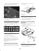
The cutting deck is designed to withstand blade impacts without deformation of the chamber. If a solid object is struck, inspect the blade for damage and blade plane for accuracy. Inspecting the Blade Plane 1 1. Remove hydraulic motor from cutting deck and remove cutting deck from tractor. 1 2. Use hoist (or minimum of two people) and place cutting deck on flat table. Figure 8 1. Motor mounting screws 3. Mark one end of blade with paint pen or marker. Use this end of blade to check all heights. 3.
Adjusting the Blade Plane Removing the Cutter Blade Start with front adjustment (change one bracket at a time). The blade must be replaced if a solid object is hit, the blade is out of balance or if the blade is bent. Always use genuine Toro replacement blades to be sure of safety and optimum performance. Never use replacement blades made by other manufacturers because they could be dangerous. 1. Remove height-of-cut bracket, (front, left, or right) from deck frame (Fig. 11). 2. Adjust .060 in.
2. Examine cutting ends of the blade carefully, especially where the flat and curved parts of the blade meet (Fig. 13-A). Since sand and abrasive material can wear away the metal that connects the flat and curved parts of the blade, check the blade before using the machine. If wear is noticed (Fig. 13-B), replace the blade; refer to Removing the Cutter Blade, page 12. 4. To check blade for being straight and parallel, lay blade on a level surface and check its ends.
Seal Removal Bearing Removal Using a 1/4 in. thick, 3 in. x 3 in. square piece of steel and the following specifications, make a seal removal tool (Fig. 16). Reference: The bearings are pressed on to the shaft (.0003–.0016 in. interference) and loose fit to housing (.0020–.0035 in. clearance). .188 in. dia. (2) 1. Remove retaining ring (Fig. 17). Repeat on other end. 2. Loosely secure roller assembly in bench vise and lightly tap one end of roller shaft until free from housing. .625 in. dia. 3.
Cutting Deck Storage If cutting deck is separated from traction unit for any length of time, install spindle plug (94-2703) in top of spindle to protect spindle from dust and water. 3 2 4 1 Figure 18 1. Front roller 2. Mounting bolt 3. Bearing 4. Bearing spacer 3. Push second bearing out in press. 4. Inspect roller housing, bearings, and bearing spacer for damage (Fig. 18). Replace damaged components and re-assemble. Assembly 1. Press first bearing into roller housing (Fig. 18).
The Toro General Commercial Products Warranty A Two-Year Limited Warranty Conditions and Products Covered The Toro Company and its affiliate, Toro Warranty Company, pursuant to an agreement between them, jointly warrant your 1996 or newer Toro Commercial Product (“Product”) purchased after January 1, 1997, to be free from defects in materials or workmanship for two years or 1500 operational hours*, whichever occurs first.