
Installation Instructions

1
All Rights Reserved
Printed in the USA
W 2004, 2007 by The Toro Company
8111 Lyndale Avenue South
Bloomington, MN 55420-1196
Rear Roller Scraper Kit
27” Rotary Cutting Unit
Model No. 30829
Form No. 3351–776 Rev A
Installation Instructions
1. Position the machine on a level surface, lower cutting
decks, stop engine, engage the parking brake and
remove key from ignition switch.
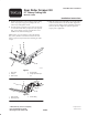
2. Loosely mount each end of scraper and a scraper plate
to each roller mount with (2) capscrews and a jam nut
(Fig. 1). The longer capscrew and jam nut are to be
installed in the lower mounting hole.
Note: If there are grease fittings on the roller mounts
(Fig. 2) they must be removed and used instead of the
longer capscrews and jam nuts when mounting the roller
scraper.
1
2
3
4
m–6676
5
Figure 1
1. Rear roller
2. Scraper
3. Roller mount
4. Scraper plate
5. Longer capscrew & jam
nut
1
2
3
Figure 2
1. Roller scraper
2. Mounting screw
3. Grease fitting
3. Slide the scraper up or down until a gap of .020–.040 in.
is achieved between the rod and the roller. Tighten the
capscrews/grease fittings to lock adjustment. Torque to
30 ft.-lb. (41 N⋅m). Tighten the jam nut against the
scraper plate, if applicable.