Form No. 3357–929 Rev B 27, Rotary Cutting Deck Groundsmaster) 3500, 4500/4700 Traction Unit Model No.
Contents Introduction . . . . . . . . . . . . . . . . . . . . . . . . . . . . . . . . . Safety . . . . . . . . . . . . . . . . . . . . . . . . . . . . . . . . . . . . . . Safety and Instruction Decals . . . . . . . . . . . . . . . . . Specifications . . . . . . . . . . . . . . . . . . . . . . . . . . . . . . . . General Specifications . . . . . . . . . . . . . . . . . . . . . Dimensions . . . . . . . . . . . . . . . . . . . . . . . . . . . . . . . Setup . . . . . . . . . . . . . . . . . . . . . . . . . . .
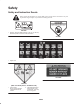
Safety Safety and Instruction Decals Safety decals and instructions are easily visible to the operator and are located near any area of potential danger. Replace any decal that is damaged or lost. 98-7818 1. Warning—torque the blade bolt to 85–110 ft.-lb (115–149 N⋅m). Read the operator’s manual for further instructions. 43-8480 104-1086 1. Height of cut 104–4892 106-6753 (Affix over decal part no. 43–8480 for CE) 1. Thrown object hazard—keep bystanders a safe distance from the machine. 2.
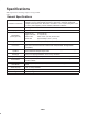
Specifications Note: Specifications and design subject to change without notice. General Specifications Chamber Construction Blade Tip Speed Blade Plane (factory pre-set) Height of Cut Welded 7 GA (.1793 in.),10 GA (.1345 in.) and 12 GA (.1036 in.) steel. Spindle support is 3/16 in. high-strength steel and 10 GA exterior channels, withstands multiple blade impact tests. Deck frame is welded 1-1/2 in. square tubing and 7 GA (.1793 in.) side supports, protects chamber, withstands collisions.
Dimensions Overall length 34 in. (86.4 cm) Overall width 34 in. (86.4 cm) Overall height 9.6 in. (24.4 cm) to carrier mount 10-1/2 in. (26.7 cm) at 3/4 in. height of cut 13-3/4 in. (34.9 cm) at 4 in. height of cut Roller footprint Front to back Rear roller Front rollers 29.5 in. (74.9 cm) 29.8 in. (75.7 cm) full length 18.5 in.
Setup Note: Determine the left and right sides of the machine from the normal operating position. Loose Parts Note: Use this chart as a checklist to ensure that all parts have been received. Without these parts, total setup cannot be completed. Description Qty. Decal 1 Parts Catalog 1 Operator’s Manual 1 Adjusting the Carrier Frame (Groundsmaster 3500 only) Use Apply to cutting deck for CE Read before operating the machine.
Adjusting the Height of Cut Important This cutting deck often cuts approximately 1/4 inch lower than a reel cutting unit with the same bench setting. It may be necessary to have these rotary cutting deck’s bench set 1/4 inch above that of reels cutting in the same area. Important Access to the rear cutting units is greatly improved by removing the cutting unit from the tractor.
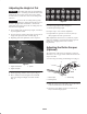
Installing the Mulching Baffle (Optional) 1. Thoroughly clean debris from mounting holes on rear wall and left side wall of chamber. 2. Install mulching baffle in rear opening and secure with 5 flange head screws (Fig. 5). 1 Figure 5 1. Mulching baffle 3. Verify that mulching baffle does not interfere with either tip of blade and does not protrude inside the surface of the rear chamber wall. Warning Do not use the high lift blade with the mulching baffle.
Operation Atomic Blade This blade was designed to provide excellent leaf mulching. Note: Determine the left and right sides of the machine from the normal operating position. Attributes: • Excellent leaf mulching Operating Tips Mow When Grass is Dry Blade Selection Mow either in the late morning to avoid the dew, which causes grass clumping, or in late afternoon to avoid the damage that can be caused by direct sunlight on the sensitive, freshly mowed grass.
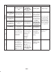
Optional Equipment Configuration Cons Pros Applicatio tion High Lift Parallel Sail Blade Standard Angle Sail DO NOT USE Blade WITH MULCHING BAFFLE Grass Cutting: .75 to 1.75 inch Height of Cut Recommended in most applications May work well in light or sparse turf Grass Cutting: 2.00 to 2.50 inch Height of Cut Recommended for thick or lush turf Recommended for light or sparse turf Grass Cutting: 2.75 to 4.
Maintenance Note: Determine the left and right sides of the machine from the normal operating position. Caution If you leave the key in the ignition switch, someone could accidently start the engine and seriously injure you or other bystanders. Remove the key from the ignition and disconnect the wire from the spark plug before you do any maintenance. Set the wire aside so that it does not accidentally contact the spark plug. Greasing the Bearings Each cutting deck has two grease fittings per rear roller.
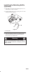
Cutting Deck Service Latch Groundsmaster 3500–D only When servicing cutting decks, use the service latch to prevent injury. 1. Center cutting deck sidewinder with the traction unit. 1 2. Raise cutting decks to transport position. 1 3. Set parking brake and turn off machine. Figure 9 4. Release latch rod (Fig. 8) from front carrier frame retainer. 1. Motor mounting screws 3. Remove lynch pin or retaining nut (GM4700 only) securing deck carrier frame to lift arm pivot pin (Fig. 10). 1 1 Figure 8 1.
Blade Plane Adjusting the Blade Plane The rotary deck comes from the factory preset at 2.00 inch height-of-cut and blade rake of 0.310 inch. The left-hand and right-hand heights are also preset to within ±0.030 inch of the other. Start with front adjustment (change one bracket at a time). The cutting deck is designed to withstand blade impacts without deformation of the chamber. If a solid object is struck, inspect the blade for damage and blade plane for accuracy. 2. Adjust .060 in. shims and/or .
Removing the Cutter Blade Inspecting and Sharpening the Blade The blade must be replaced if a solid object is hit, the blade is out of balance or if the blade is bent. Always use genuine Toro replacement blades to be sure of safety and optimum performance. Never use replacement blades made by other manufacturers because they could be dangerous. 1. Raise cutting deck to highest position, shut the engine off, and engage the parking brake. Block cutting deck to prevent it from falling accidentally.
SHARPEN AT THIS ANGLE ONLY 3 2 END VIEW Figure 15 4. To check blade for being straight and parallel, lay blade on a level surface and check its ends. Ends of blade must be slightly lower than the center, and cutting edge must be lower than the heel of the blade. This blade will produce good quality of cut and require minimal power from the engine. By contrast a blade that is higher at the ends than the center, or if cutting edge is higher than the heel, the blade is bent or warped and must be replaced.
The Toro General Commercial Products Warranty A Two-Year Limited Warranty Conditions and Products Covered The Toro Company and its affiliate, Toro Warranty Company, pursuant to an agreement between them, jointly warrant your Toro Commercial Product (“Product”) to be free from defects in materials or workmanship for two years or 1500 operational hours*, whichever occurs first.