
Operator's Manual


12
Blade Plane
The rotary deck comes from the factory preset at 2.00 inch
height-of-cut and blade rake of 0.310 inch. The left-hand
and right-hand heights are also preset to within ±0.030 inch
of the other.
The cutting deck is designed to withstand blade impacts
without deformation of the chamber. If a solid object is
struck, inspect the blade for damage and blade plane for
accuracy.
Inspecting the Blade Plane
1. Remove hydraulic motor from cutting deck and remove
cutting deck from tractor.
2. Use hoist (or minimum of two people) and place cutting
deck on flat table.
3. Mark one end of blade with paint pen or marker. Use
this end of blade to check all heights.
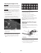
4. Position cutting edge of marked end of blade at 12
o’clock (straight ahead in direction of mowing)
(Fig. 11) and measure height from table to cutting edge
of blade.
12 o’clock
6 o’clock
9 o’clock
3 o’clock
Figure 11
5. Rotate marked end of blade to the 3 and 9 o’clock
positions (Fig. 11) and measure heights.
6. Compare 12 o’clock measured height to the height of
cut setting. It should be within .030 inch. The 3 and 9
o’clock heights should be .150±.090 inch higher than
the 12 o’clock setting and within .090 in. of each other.
If any of these measurements are not within specification,
proceed to Adjusting the Blade Plane, page 12.
Adjusting the Blade Plane
Start with front adjustment (change one bracket at a time).
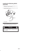
1. Remove height-of-cut bracket, (front, left, or right)
from deck frame (Fig. 12).
2. Adjust .060 in. shims and/or .030 in. shim between the
deck frame and bracket to achieve the desired height
setting (Fig. 12).
1
2
Figure 12
1. Height of cut bracket 2. Shims
3. Install height-of-cut bracket to deck frame with
remaining shims assembled below the height-of-cut
bracket.
4. Secure socket head bolt/spacer and flange nut.
Note: Socket head bolt/spacer are held together with
Loctite to prevent spacer from falling inside the deck
frame.
5. Verify 12 o’clock height and adjust if needed.
6. Determine if only one or both (right-hand and left-hand)
height-of-cut brackets need to be adjusted. If the 3 or 9
o’clock side is .150±.090 in. higher than the new front
height then no adjustment is needed for that side. Adjust
other side to within ±.090 in. of correct side.
7. Adjust right and/or left height-of-cut brackets by
repeating steps 1 thru 3.
8. Secure carriage bolts and flange nuts.
9. Again, verify 12, 3, and 9 o’clock heights.