Form No. 3393-163 Rev A 27in Rotary Cutting Unit Groundsmaster® 3500-D/3505-D/4500-D/4700-D Model No. 30834—Serial No. 315000001 and Up Register at www.Toro.com.
Contents This product complies with all relevant European directives. For details, please see the Declaration of Incorporation (DOI) at the back of this publication. Safety ........................................................................... 3 Safety and Instructional Decals ................................. 3 Setup ............................................................................ 4 Adjusting the Carrier Frame (Groundsmaster 3500-D and 3500-G only) .....................................
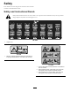
Safety This machine has been designed in accordance with EN ISO 5395:2013 and ANSI B71.4-2012. Safety and Instructional Decals Safety decals and instructions are easily visible to the operator and are located near any area of potential danger. Replace any decal that is damaged or lost. 104-1086 1. Height of cut 93-7818 1. Warning—read the Operator's Manual for instructions on torquing the blade bolt/nut to 115-149 N-m (85-110 ft-lb). 117-4764 1.
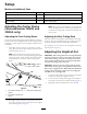
Setup Media and Additional Parts Description Use Qty. CE Decal 1 Apply to the cutting deck for CE compliance. Operator's Manual 1 Read before operating. Parts Catalog 1 Use to lookup parts. Adjusting the Carrier Frame (Groundsmaster 3500-D and 3500-G only) Note: This increases the chamber to carrier clearance due to the higher position of the cutting chamber, but will cause the cutting deck to reach their maximum up travel sooner.
1 2 3 G011346 Figure 5 1. Roller spacer 3. Grease fitting 2. Mounting screw 2. Slide the scraper up or down until a gap of 0.020 to 0.040 inch (0.5 to 1 mm) is achieved between the rod and the roller. Figure 3 1. Height of cut bracket 3. Spacer 3. Secure the grease fitting and screw to 30 ft-lb (41 N-m) in an alternating sequence. 2. Height of cut plate 4. While supporting the chamber, remove the spacer (Figure 3). Installing the Mulching Baffle (Optional) 5.
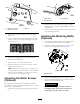
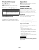
Product Overview Operation Specifications Note: Determine the left and right sides of the machine from the normal operating position. Note: Specifications and design are subject to change without notice. Selecting a Blade Dimensions and Weights (approx.) Length 34 inches (86.4 cm) Width 34 inches (86.4 cm) Height 9.6 inches (24.4 cm) to carrier mount 10–1/2 inches (26.7 cm) at 3/4 inch height of cut 13–3/4 inches (34.
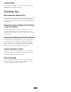
Atomic Blade This blade was designed to provide excellent leaf mulching. Attributes: Excellent leaf mulching Operating Tips Mow when the Grass is Dry Mow either in the late morning to avoid the dew, which causes grass clumping, or in late afternoon to avoid the damage that can be caused by direct sunlight on the sensitive, freshly mowed grass. Select the Proper Height-of-Cut Setting to Suit Conditions Remove approximately one inch or no more than 1/3 of the grass blade when cutting.
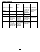
Choosing Accessories Optional Equipment Configuration Angle Sail Blade High Lift Parallel Sail Blade Do not use with the mulching baffle Mulching Baffle Roller Scraper Grass Cutting: 0.75 to 1.75 inch (1.9 to 4.4 cm) Height-of-Cut Recommended in most applications May work well in light or sparse turf Grass Cutting: 2.00 to 2.50 inch (5 to 6.4 cm) Height-of-Cut Recommended for thick or lush turf Recommended for light or sparse turf Grass Cutting: 2.75 to 4.
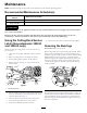
Maintenance Note: Determine the left and right sides of the machine from the normal operating position. Recommended Maintenance Schedule(s) Maintenance Service Interval Before each use or daily Every 50 hours Maintenance Procedure • Check the blade stopping time. • Grease the bearings CAUTION If you leave the key in the ignition switch, someone could accidently start the engine and seriously injure you or other bystanders.
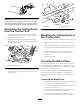
G011349 Figure 9 Important: Make sure the grease groove in each roller mount aligns with the grease hole in each end of the roller shaft. To help align the groove and hole, there is also an alignment mark on one end of the roller shaft. Figure 11 1. Lynch pin Separating the Cutting Decks from the Traction Unit 2. Lift arm pivot pin 4. Roll the cutting deck away from the traction unit. 1.
mowing) (Figure 12) and measure height from table to cutting edge of blade. 3. Install the height-of-cut bracket to the deck frame with the remaining shims assembled below the height-of-cut bracket. 12:00 4. Secure the socket head bolt/spacer and flange nut. Note: Socket head bolt/spacer are held together with Loctite to prevent the spacer from falling inside the deck frame. 3:00 9:00 6:00 Figure 12 5. Verify the 12 o’clock height and adjust if needed. 6.
3. Inspect the cutting edges of all blades. Sharpen the cutting edges if they are dull or nicked. Sharpen only the top of the cutting edge and maintain the original cutting angle to make sure of sharpness (Figure 16). The blade will remain balanced if the same amount of metal is removed from both cutting edges. DANGER A worn or damaged blade can break, and a piece of the blade could be thrown into the operator’s or bystander’s area, resulting in serious personal injury or death.
Storage 2. Insert a punch through the end of the roller housing and drive the opposite bearing out by alternating taps to the opposite side of inner bearing race. There should be a 0.060 inch (1.5 mm) lip of inner race exposed. If the cutting deck is separated from the traction unit for any length of time, install a spindle plug in the top of the spindle to protect the spindle from dust and water. 3 2 4 1 G011356 Figure 17 1. Front roller 3. Bearing 2. mounting bolt 4. Bearing spacer 3.
Notes: 14
Declaration of Incorporation Model No. 30834 Serial No. 315000001 and Up Product Description 27in Rotary Cutting Unit, Groundsmaster 3500-D/3505-D/4500-D/4700-D Invoice Description General Description Directive CONTOUR PLUS II CUTTING DECK 27in Rotary Cutting Unit 2006/42/EC, 2000/14/EC Relevant technical documentation has been compiled as required per Part B of Annex VII of 2006/42/EC.
Toro General Commercial Product Warranty A Two-Year Limited Warranty Conditions and Products Covered The Toro Company and its affiliate, Toro Warranty Company, pursuant to an agreement between them, jointly warrant your Toro Commercial product (“Product”) to be free from defects in materials or workmanship for two years or 1500 operational hours*, whichever occurs first. This warranty is applicable to all products with the exception of Aerators (refer to separate warranty statements for these products).