
Operator's Manual

G01 1349
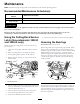
Figure9
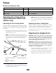
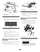
Important:Makesurethegreasegrooveineachroller
mountalignswiththegreaseholeineachendofthe
rollershaft.Tohelpalignthegrooveandhole,thereis
alsoanalignmentmarkononeendoftherollershaft.
SeparatingtheCuttingDecks
fromtheTractionUnit
1.Positionthemachineonalevelsurface,lowerthe
cuttingdeckstotheoor,shuttheengineoff,and
engagetheparkingbrake.
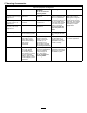
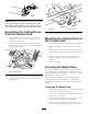
2.Disconnectandremovethehydraulicmotorfrom
thedeck(Figure10).Coverthetopofthespindleto
preventcontamination.
Figure10
1.Motormountingscrews
3.Removethelynchpinorretainingnut(GM4700only)
securingthedeckcarrierframetotheliftarmpivot
pin(Figure11).
Figure11
1.Lynchpin
2.Liftarmpivotpin
4.Rollthecuttingdeckawayfromthetractionunit.
MountingtheCuttingDecksto
theTractionUnit
1.Positionmachineonalevelsurfaceandshutengineoff.
2.Movecuttingdeckintopositioninfrontoftraction
unit.
3.Slidedeckcarrierframeontoliftarmpivotpin.Secure
withlynchpinorretainingnut(GM4700only)(Figure
11).
4.Installthehydraulicmotortothedeck(Figure10).
MakesurethattheO-ringisinpositionandnot
damaged.
5.Greasethespindle.
ServicingtheBladePlane
Therotarydeckcomesfromthefactorypresetat2.00inch
(5cm)height-of-cutandbladerakeof0.310inch(7.9mm).
Theleft-handandright-handheightsarealsopresettowithin
±0.030inch(0.7mm)oftheother.
Thecuttingdeckisdesignedtowithstandbladeimpacts
withoutdeformationofthechamber.Ifasolidobjectis
struck,inspectthebladefordamageandthebladeplanefor
accuracy.
InspectingtheBladePlane
1.Removethehydraulicmotorfromthecuttingdeckand
removethecuttingdeckfromthetractor.
2.Useahoist(orminimumoftwopeople)andplacethe
cuttingdeckonaattable.
3.Markoneendofthebladewithapaintpenormarker.
Usethisendofthebladetocheckallheights.
4.Positionthecuttingedgeofthemarkedendofthe
bladeat12o’clock(straightaheadinthedirectionof
10