
Operator's Manual

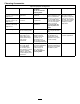


mowing)(Figure12)andmeasureheightfromtable
tocuttingedgeofblade.
G01 1353
6:00
12:00
9:00
3:00
Figure12
5.Rotatethemarkedendofthebladetothe3and9
o’clockpositions(Figure12)andmeasuretheheights.
6.Comparethe12o’clockmeasuredheighttothe
height-of-cutsetting.Itshouldbewithin0.030inch
(0.7mm).The3and9o’clockheightsshouldbe
0.150±.090inch(3.8±2.2mm)higherthanthe12
o’clocksettingandwithin0.090inch(2.2mm)ofeach
other.
Ifanyofthesemeasurementsarenotwithinspecication,
proceedtoAdjustingtheBladePlane.
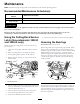
AdjustingtheBladePlane
Startwiththefrontadjustment(changeonebracketatatime).
1.Removetheheight-of-cutbracket,(front,left,orright)
fromthedeckframe(Figure13).
2.Adjust0.060inch(1.5mm)shimsand/or0.030inch
(0.7mm)shimbetweenthedeckframeandbracketto
achievethedesiredheightsetting(Figure13).
Figure13
1.Heightofcutbracket2.Shims
3.Installtheheight-of-cutbrackettothedeckframewith
theremainingshimsassembledbelowtheheight-of-cut
bracket.
4.Securethesocketheadbolt/spacerandangenut.
Note:Socketheadbolt/spacerareheldtogetherwith
Loctitetopreventthespacerfromfallinginsidethe
deckframe.
5.Verifythe12o’clockheightandadjustifneeded.
6.Determineifonlyoneorboth(right-handand
left-hand)height-of-cutbracketsneedtobeadjusted.
Ifthe3or9o’clocksideis0.150±0.090inch(3.8±2.2
mm)higherthanthenewfrontheightthenno
adjustmentisneededforthatside.Adjusttheother
sidetowithin±0.090inch(2.2mm)ofthecorrectside.
7.Adjusttherightand/orleftheight-of-cutbracketsby
repeatingsteps1through3.
8.Securethecarriageboltsandangenuts.
9.Again,verifythe12,3,and9o’clockheights.
RemovingtheCutterBlade
Theblademustbereplacedifasolidobjectishit,theblade
isoutofbalance,orifthebladeisbent.Alwaysusegenuine
Tororeplacementbladestobesureofsafetyandoptimum
performance.Neverusereplacementbladesmadebyother
manufacturersbecausetheycouldbedangerous.
1.Raisethecuttingdecktothehighestposition,shutthe
engineoff,andengagetheparkingbrake.Blockthe
cuttingdecktopreventitfromfallingaccidentally.
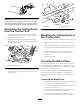
2.Grasptheendofthebladeusingaragorthickly
paddedglove.Removethebladebolt,anti-scalpcup,
andbladefromthespindleshaft(Figure14).
G01 1355
1
2
Figure14
1.Bladebolt2.Anti-scalpcup
3.Installtheblade,sailfacingtowardthecuttingdeck,
withtheanti-scalpcupandbladebolt(Figure14).
Tightenbladeboltto85–110ft-lb(115–149N-m).
11