
Operator's Manual
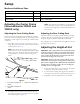
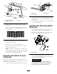

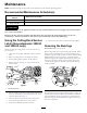
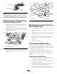

Figure3
1.Heightofcutbracket3.Spacer
2.Heightofcutplate
4.Whilesupportingthechamber,removethespacer
(Figure3).
5.Movethechambertothedesiredheight-of-cutand
installaspacerintothedesignatedheight-of-cuthole
andslot(Figure4).
Figure4
6.Positionthetappedplateinlinewiththespacer.
7.Installtheboltngertight.
8.Repeatsteps4–7foreachsideadjustment.
9.Tightenallthreeboltsto30ft-lb(41N-m).Always
tightenthefrontboltrst.
Note:Adjustmentsofmorethan1-1/2inches(3.8
cm)mayrequiretemporaryassemblytoanintermediate
heighttopreventbinding(e.g.changingfrom1.25to
2.75inch(3.1to7cm)height-of-cut).
AdjustingtheRollerScraper
(Optional)
Theoptionalrearrollerscraperisdesignedtoworkbest
whenthereisanevengapof0.020–0.040inch(0.5to1mm)
betweenthescraperandroller.
1.Loosenthegreasettingandmountingscrew(Figure
5).
G01 1346
1
2
3
Figure5
1.Rollerspacer
3.Greasetting
2.Mountingscrew
2.Slidethescraperupordownuntilagapof0.020to
0.040inch(0.5to1mm)isachievedbetweentherod
andtheroller.
3.Securethegreasettingandscrewto30ft-lb(41N-m)
inanalternatingsequence.
InstallingtheMulchingBafe
(Optional)
1.Thoroughlycleandebrisfromthemountingholeson
therearwallandleftsidewallofthechamber.
2.Installthemulchingbafeintherearopeningand
secureitwith5angeheadbolts(Figure6).
G01 1347
1
Figure6
1.Mulchingbafe
3.Verifythatmulchingbafedoesnotinterferewith
thetipofthebladeanddoesnotprotrudeinsidethe
surfaceoftherearchamberwall.
WARNING
Donotusethehighliftbladewiththe
mulchingbafe.Thebladecouldbreak,
resultinginpersonalinjuryordeath.
5