
Operator's Manual
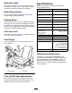

g008876
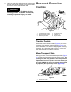
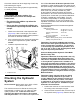
Figure11
cuttingunitsremovedforclarity
1.Liftarm3.Clearance
2.Floorplatebracket
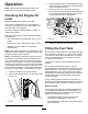
Iftheclearanceisnotinthisrange,adjustitas
follows:
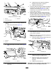
A.Backoffthestopbolts(Figure12).
g008877
Figure12
1.Stopbolt3.Clearance
2.Liftarm
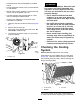
B.Backoffthejamnutonthecylinder(Figure
13).
g008878
Figure13
1.Frontcylinder2.Jamnut
C.Removethepinfromtherodendandrotate
theclevis.
D.Installthepinandchecktheclearance.
Repeattheprocedureifrequired.
E.Tightentheclevisjamnut.
2.Checktomakesurethattheclearancebetween
eachliftarmandstopboltis0.13to1.02mm
(0.005to0.040inches)(Figure12).Ifthe
clearanceisnotinthisrange,adjustthestop
boltstoattainclearance.
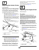
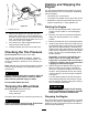
3.Starttheengine,raisethecuttingunits,and
checktomakesurethattheclearancebetween
thewearstraponthetopoftherearcuttingunit
wearbarandthebumperstrapis0.51to2.54
mm(0.02to0.10inches)(Figure14).
g008879
Figure14
1.Wearbar2.Bumperstrap
Iftheclearanceisnotinthisrange,adjustthe
rearcylinderasfollows:
Note:Iftherearliftarmclunksduringtransport,
clearancecanbereduced.
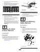
A.Lowerthecuttingunitsandbackoffthejam
nutonthecylinder(Figure15).
g008880
Figure15
1.Rearcylinder2.Adjustingnut
B.Graspthecylinderrodclosetothenutwith
apliersandragandrotatetherod.
C.Raisethecuttingunitsandcheckthe
clearance.Repeattheprocedureif
required.
D.Tightentheclevisjamnut.
Important:Lackofclearanceatthefrontstopsor
rearwearbarcoulddamagetheliftarms.
21