Form No. 3397-962 Rev B Groundsmaster® 3500-D/3505-D Rotary Mower Model No. Model No. Model No. Model No. Register at www.Toro.com. Original Instructions (EN) 30807—Serial No. 30839—Serial No. 30843—Serial No. 30849—Serial No.
This product complies with all relevant European directives; for details, please see the separate product specific Declaration of Conformity (DOC) sheet. You may contact Toro directly at www.Toro.com for product and accessory information, help finding a dealer, or to register your product.
Contents Servicing the Engine Oil.................................... 39 Servicing the Air Cleaner .................................. 41 Fuel System Maintenance ................................... 43 Draining the Fuel Tank ...................................... 43 Servicing the Water Separator .......................... 43 Bleeding the Fuel System ................................. 43 Bleeding Air from the Injectors .......................... 44 Electrical System Maintenance ...........................
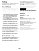
Safety Sound Pressure Level This machine has been designed in accordance with EN ISO 5395:2013 and ANSI B71.4-2012. This unit has a sound pressure level at the operator’s ear of 90 dBA, which includes an Uncertainty Value (K) of 1 dBA. General Safety Sound pressure level was determined according to the procedures outlined in EN ISO 5395:2013. This product is capable of amputating hands and feet and of throwing objects. Always follow all safety instructions to avoid serious personal injury.
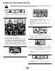
Safety and Instructional Decals Safety decals and instructions are easily visible to the operator and are located near any area of potential danger. Replace any decal that is damaged or lost. decal94-3353 94-3353 1. Crushing hazard of hand—keep your hands a safe distance away. decal93-7276 93-7276 1. Explosion hazard—wear eye protection. 2. Caustic liquid/chemical burn hazard—to perform first aid, flush with water. 3. Fire hazard—no fire, open flames, or smoking. 4.
decal104-1086 104-1086 1. Height of cut decal106-6755 106-6755 1. Engine coolant under pressure 3. Warning—do not touch the hot surface. 2. Explosion hazard—read the Operator's Manual. 4. Warning—read the Operator's Manual.
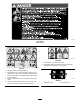
decal108-9015 108–9015 (Model 30849) decal106-6754 106-6754 1. Warning—do not touch the hot surface. 2. Cutting/dismemberment hazard, fan and entanglement hazard, belt—stay away from moving parts. decal104-5181 104-5181 1. Warning—read the Operator’s Manual. 2. Tipping hazard—do not drive on slopes greater than 15 degrees and, if the roll bar is installed, wear the seat belt. 99-3444 3. Thrown object hazard—keep bystanders a safe distance from the machine. 4.
decalbatterysymbols Battery Symbols Some or all of these symbols are on your battery 1. Explosion hazard 6. Keep bystanders a safe distance from the battery. 2. No fire, open flame, or smoking 7. Wear eye protection; explosive gases can cause blindness and other injuries. 3. Caustic liquid/chemical burn hazard 4. Wear eye protection 8. Battery acid can cause blindness or severe burns. 9. Flush eyes immediately with water and get medical help fast. 5. Read the Operator's Manual.
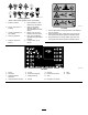
decal117-5103 117-5103 (Models 30839, 30843, and 30849) decal121-3532 121-3532 (Model 30807) 1. Read the Operator’s Manual. 4. Optional light—15A 2. SCM-2A 5. System gauges—10A 3. Main—15A 6.
decal121-3580 121-3580 (Models 30807, 30839, and 30843) 8. Engine—stop 1. Push down to disengage the PTO. 9. Engine—run 2. Pull up to engage the PTO. 3. Lower the deck. 10. Engine—run 4. Raise the deck. 11. For more information on starting the engine, read the Operator’s Manual—1) Sit in the operator’s position; 2) Turn the ignition key to the engine run position; 3) Wait for the engine preheat light to turn off; 4) Turn the ignition key to the engine start position; 5) Disengage the parking brake.
decal121-3581 121-3581 (Model 30849) 1. Push down to disengage the PTO. 7. Engine—run 2. Pull up to engage the PTO. 8. Engine—run 3. Lower the deck. 9. For more information on starting the engine, read the Operator’s Manual—1) Sit in the operator’s position; 2) Turn the ignition key to the engine run position; 3) Wait for the engine preheat light to turn off; 4) Turn the ignition key to the engine start position; 5) Disengage the parking brake. 4. Raise the deck. 10.
Setup Loose Parts Use the chart below to verify that all parts have been shipped. Procedure Description Use Qty. 1 No parts required – Activate, charge, and connect the battery. 2 Inclinometer 1 Check the angle indicator (Models 30807, 30839, and 30843 only). Warning decal (104-5181) Warning decal (99-3558) Warning decal (107-1972) Lock bracket Rivet Washer Screw (1/4 x 2 inches) Locknut (1/4 inch) Exhaust guard Self-tapping screw 1 1 3 1 2 1 1 1 1 4 No parts required – Adjust the lift arms.
1 Activating, Charging, and Connecting the Battery No Parts Required Procedure g031567 Figure 3 1. Battery cover WARNING CALIFORNIA Proposition 65 Warning Battery posts, terminals, and related accessories contain lead and lead compounds, chemicals known to the State of California to cause cancer and reproductive harm. Wash hands after handling. 2. Remove the filler caps from the battery and slowly fill each cell until the electrolyte is just above the plates. 3.
WARNING 2 Incorrect battery cable routing could damage the tractor and cables, causing sparks. Sparks can cause the battery gases to explode, resulting in personal injury. Checking the Angle Indicator • Always disconnect the negative (black) battery cable before disconnecting the positive (red) cable. Models 30807, 30839, and 30843 Only • Always connect the positive (red) battery cable before connecting the negative (black) cable. Parts needed for this procedure: 1 Inclinometer Procedure 1.
3 Installing the CE Decals Parts needed for this procedure: 1 Warning decal (104-5181) 1 Warning decal (99-3558) 3 Warning decal (107-1972) g031570 Figure 6 Procedure 1. Rivets If this machine will be used for CE, affix the CE-warning decals over the corresponding English warning decals. 2. Hood-latch bracket 3. Remove the hood-latch bracket from the hood. 4. While aligning the mounting holes, position the lock bracket and the hood-latch bracket onto the hood (Figure 7).
5 Installing the Exhaust Guard CE Models Only g012630 Figure 8 Parts needed for this procedure: 1. Hood latch 8. 1 Exhaust guard 4 Self-tapping screw Install the bolt into the other arm of the hood-lock bracket to lock the latch in position (Figure 9). Procedure Note: Tighten the bolt securely, but do not tighten the nut. 1. Position the exhaust guard around the muffler while aligning the mounting holes with the holes in the frame (Figure 10). g012631 Figure 9 1. Bolt 3.
B. 6 Back off the jam nut on the cylinder (Figure 13). Adjusting the Lift Arms No Parts Required Procedure 1. Start the engine, raise the cutting units, and ensure that the clearance between each lift arm and the floor-plate bracket is 5 to 8 mm (0.18 to 0.32 inches) as shown in Figure 11. g031573 Figure 13 1. Jam nut 2. Front cylinder C. Remove the pin from the rod end and rotate the clevis. D. Install the pin and check the clearance. Note: Repeat the procedure if required. E. 2.
g031575 Figure 15 1. Rear cylinder 2. Adjusting nut B. Grasp the cylinder rod close to the nut with a pliers and rag, and rotate the rod. C. Raise the cutting units and check the clearance. g031576 Figure 16 1. Upper, front deck mounting hole Note: Repeat the procedure if required. D. 3. Rear deck mounting hole 2. Lower, front deck mounting hole Tighten the clevis jam nut. Important: Lack of clearance at the front stops or rear wear bar could damage the lift arms. 2.
bench set 6 mm (1/4 inch) above that of the reels cutting in the same area. 8. Repeat steps 4 to 7 for each side adjustment. 9. Tighten the 3 bolts to 41 N∙m (30 ft-lb). Important: Access to the rear cutting units is Note: Tighten the front bolt first. greatly improved by removing the cutting unit from the machine. If the machine is equipped with a Sidewinder® unit, side-wind the cutting units to the right, remove the rear cutting unit, and slide it out to the right side. 1.
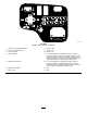
Product Overview 10 Controls Installing the Mulching Baffle Optional No Parts Required Procedure 1. Thoroughly clean debris from the mounting holes on the rear wall and left wall of the chamber. 2. Install the mulching baffle in the rear opening and secure it with 5 flange-head bolts (Figure 20). g031595 Figure 21 1. Tilt-steering lever 4. Forward traction pedal 2. Angle indicator 5. Mow/transport slide 3. Reverse traction pedal 6.
g031596 Figure 22 1. Speed-stop screw Tilt-Steering Lever Pull the tilt-steering lever back to tilt the steering wheel to the desired position, then push the lever forward to tighten (Figure 21). g031597 Figure 23 Indicator Slot 1. Parking brake 7. Glow-plug-indicator light 2. Cutting-unit-shift lever 8. Hour meter 3. Cutting-unit-drive switch 9. Throttle Models 30807, 30839, and 30849 Only 4. Alternator light 10.
Fuel Gauge For Models 30807, 30839, and 30849, move the lever to the right or left to move the cutting units in the same direction. The fuel gauge registers the amount of fuel in the tank (Figure 24). Note: Do this only when the cutting units are raised or if they are on the ground and the machine is moving. Note: The lever does not need to be held in the forward position while you are lowering the cutting units.
Specifications Operation Note: Specifications and design are subject to Note: Determine the left and right sides of the machine from the normal operating position. change without notice. Traction Unit Overall width: 68-inch width of cut 182 cm (71.8 inches) Overall width: 72-inch width of cut 193 cm (75.8 inches) Length Height to top of the ROPS Before Operation Safety 295 cm (116 inches) 180 cm (70.8 inches) Wheel base 149 cm) (58.
Fuel Safety overfill the fuel tank. Replace the fuel-tank cap and tighten it securely. DANGER Selecting a Blade In certain conditions, fuel is extremely flammable and highly explosive. A fire or explosion from fuel can burn you and others and can damage property. • Fill the fuel tank outdoors, in an open area, when the engine is cold. Wipe up any fuel that spills. • Never fill the fuel tank inside an enclosed trailer.
Using an Atomic Blade Attributes: This blade provides excellent leaf mulching. Selecting Accessories Optional-Equipment Configurations Angle-Sail Blade High-Lift-Parallel Sail Blade (Do not use with the mulching baffle) Grass cutting: 1.9 to 4.4 cm (0.75 to 1.75 inches) height of cut Recommended in most applications May work well in light or sparse turf Grass cutting: 5 to 6.4 cm (2 to 2.
Use summer grade diesel fuel (No. 2-D) at temperatures above -7° C (20° F) and winter grade (No. 1-D or No. 1-D/2-D blend) below that temperature. DANGER Low tire pressure decreases machine side-hill stability. This could cause a rollover, which may result in personal injury or death. Using winter grade fuel at lower temperatures provides lower flash point and cold flow characteristics which will ease starting and reduce fuel filter plugging. Do not underinflate the tires.
• Keep all body parts, including hands and feet, CAUTION away from all moving parts. If the safety-interlock switches are disconnected or damaged, the machine could operate unexpectedly and cause personal injury. • Do not tamper with the safety systems. • Check the operation of the switches daily and replace any damaged switches before operating the machine. 1. Drive the machine slowly to a large, open area.. 2. Lower the cutting unit(s), shut off the engine, and engage the parking brake. 3.
Starting and Stopping the Engine – Stop the machine on level ground. – Disengage the power take-off and lower the attachments. – Set the parking brake. Starting the Engine – Shut off the engine and remove the key. – Wait for all moving parts to stop. 1. overspeed the engine. Operating the engine at excessive speed may increase the potential for personal injury. Ensure that the parking brake is set and the cutting-unit-drive switch is in the DISENGAGE position. 2.
Standard-Control Module (SCM) The Standard-Control Module (SCM) is a potted electronic device produced in a 1-size-fits-all configuration. The module uses solid state and mechanical components to monitor and control standard, electrical features required for safe product operation. The module-monitor input includes neutral, parking brake, PTO, start, backlap, and high temperature. The module energizes outputs including PTO, Starter, and ETR (energize to run) solenoid.
Each row (across) in the logic chart below identifies input and output requirements for each specific product function. Product functions are listed in the left column. Symbols identify specific circuit condition, including energized to voltage, closed to ground, and open to ground.
Understanding Counterbalance Mowing When the Grass Is Dry The counterbalance system maintains hydraulic back pressure on the deck-lift cylinders. This counterbalance pressure transfers mower deck weight to the mower drive wheels to improve traction. The counterbalance pressure has been set at the factory to an optimal balance of after-cut appearance and traction capability in most turf conditions.
Towing the Traction Unit After Operation Important: In an emergency, you can tow the machine for a short distance. Do not tow the machine at faster than 3 to 4 km/h (2 to 3 mph); otherwise, you may damage the drive system. If you must move the machine a considerable distance, transport it on a truck or trailer. After Operation Safety General Safety • Clean grass and debris from the cutting units, 1. drives, mufflers, and engine to help prevent fires. Clean up oil or fuel spills.
Maintenance Note: Determine the left and right sides of the machine from the normal operating position. Recommended Maintenance Schedule(s) Maintenance Service Interval After the first hour Maintenance Procedure • Torque the wheel-lug nuts. After the first 10 hours • Torque the wheel-lug nuts. • Check the condition and tension of all belts. • Change the hydraulic filter. After the first 50 hours • Change the engine oil and engine-oil filter.
Daily Maintenance Checklist Duplicate this page for routine use. For the week of: Maintenance Check Item Monday Tuesday Wednesday Thursday Friday Saturday Check the safety-interlock operation. Check the brake operation. Check the engine-oil level. Check the cooling-system-fluid level. Drain the water/fuel separator. Check the air filter, dust cup, and burp valve. Check for unusual engine noises.2 Check the radiator and screen for debris Check for unusual operating noises.
Service-Interval Chart decal117-5103 Figure 29 Pre-Maintenance Procedures 8. • Whenever you park or store the machine, or leave it unattended, lower the cutting units unless you use a positive mechanical lock. Pre-Maintenance Safety • If possible, do not perform maintenance on the machine while the engine is running.
Using the Cutting Deck Service Latch made by other manufacturers could be dangerous, and such use could void the product warranty. Preparing the Machine for Maintenance When servicing the cutting decks, use the service latch to prevent injury. 1. Center the cutting deck sidewinder with the traction unit. 1. Ensure that the PTO is disengaged. 2. Park the machine on a level surface. 2. Raise the cutting decks to the transport position. 3. Set the parking brake. 3.
Lubrication Greasing the Bearings and Bushings Service Interval: Every 50 hours—Lubricate all of the bearings and bushings. Every 500 hours/Yearly (whichever comes first) The machine has grease fittings that you must lubricate regularly with No. 2 lithium grease. Also, lubricate the machine immediately after every washing.
• 2 left, front lift-arm pivots and lift cylinder (Figure • Mow/transport slide (Figure 40) 37) g008902 Figure 40 • Belt-tension pivot (Figure 41) g008899 Figure 37 • 2 right, front lift-arm pivots and lift cylinder (Figure 38) g008903 Figure 41 g008900 • Steering cylinder (Figure 42). Figure 38 • Neutral-adjustment mechanism (Figure 39) g008904 Figure 42 g008901 Figure 39 Note: If desired, an additional grease fitting may be installed at the other end of the steering cylinder.
Engine Maintenance Engine Safety Shut off the engine before checking the oil or adding oil to the crankcase. Servicing the Engine Oil g008905 Figure 43 Checking the Engine-Oil Level Service Interval: Before each use or daily • 2 (per cutting unit) cutting unit spindle-shaft bearings (Figure 44) The engine is shipped with oil in the crankcase; however, check the oil level before and after you start the engine for the first time. Note: You can use either fitting, whichever is more accessible.
4. Change the engine-oil filter as shown in Figure 48. g029301 Figure 46 Changing the Engine Oil and Filter Service Interval: After the first 50 hours g027477 Figure 48 Every 150 hours 1. Start the engine and let it run 5 minutes to allow the oil to warm up. 2. With the machine parked on a level surface, stop the engine, remove the key, and wait for all moving parts to stop before leaving the operating position. 3. Change the engine oil as shown in Figure 47.
Servicing the Air Cleaner Check the air-cleaner body for damage that could cause an air leak and replace it if it is damaged. Check the entire intake system for leaks, damage, or loose hose clamps. Also, inspect the rubber intake-hose connections at the air cleaner and turbocharger to ensure that the connections are complete. Ensure that the cover is seated correctly and seals with the air-cleaner body.
Servicing the Air-Cleaner Filter Service Interval: Every 200 hours (More frequently in extreme dusty or dirty conditions) 1. Before removing the filter, use clean and dry, low-pressure air (275 kPa or 40 psi) to help remove large accumulations of debris packed between the outside of the primary filter and the canister. Important: Avoid using high-pressure air that could force dirt through the filter and into the intake tract, causing damage.
Replacing the Fuel Filter Fuel System Maintenance Draining the Fuel Tank Service Interval: Every 1,000 hours—Drain and clean the fuel tank. 1. Clean the area where the filter mounts (Figure 52). 2. Remove the filter and clean the mounting surface. 3. Lubricate the gasket on the filter with clean oil. 4. Install the filter by hand until the gasket contacts the mounting surface; then rotate an additional 1/2 turn. Every 2 years—Drain and clean the fuel tank.
forcing air out around the air-bleed screw. Leave the key in the ON position until a solid stream of fuel flows out around the screw. Electrical System Maintenance Tighten the screw and turn the key to the OFF position. Electrical System Safety Note: The electric fuel pump will operate, 6. • Disconnect the battery before repairing the Note: Normally, the engine should start after machine. Disconnect the negative terminal first and the positive last.
Maintain the battery-electrolyte level properly and keep the top of the battery. If you store the machine in a hot location, the battery will discharge more rapidly than if you store the machine in a cool location. Drive System Maintenance Maintain the cell level with distilled or demineralized water. Do not fill the cells above the bottom of the split ring inside each cell. Install the filler caps with the vents pointing to the rear (toward the fuel tank).
Cooling System Maintenance WARNING The engine must be running so that you can make a final adjustment of the traction adjustment cam. Contact with hot or moving parts can result in personal injury. Cooling System Safety Keep your hands, feet, face, and other body parts away from the muffler, other hot parts of the engine, and rotating parts. 5. Start the engine and rotate the cam hex in both directions to determine the mid position of the neutral span. 6. Tighten the locknut securing the adjustment.
g031618 Figure 57 1. Expansion tank g031617 Figure 56 1. Oil cooler 2. Access panel 2. 3. Radiator If the coolant level is low, remove the expansion-tank cap and replenish the system. Note: Do not overfill. 3. Clean the radiator hourly if conditions are extremely dusty and dirty; refer to Cleaning the Cooling System (page 48). The cooling system is filled with a 50/50 solution of water and permanent ethylene glycol anti-freeze.
Brake Maintenance Cleaning the Cooling System Adjusting the Parking Brake Service Interval: Before each use or daily 1. Turn the engine off and raise the hood. 2. Clean the engine area thoroughly of all debris. 3. Remove the access panel (Figure 58). Service Interval: Every 200 hours—Check the parking-brake adjustment. 1. Loosen the set screw securing the knob to the parking-brake lever (Figure 60). g031637 Figure 60 1. Knob 3. Parking-brake lever 2. Set screw g031619 Figure 58 1.
Belt Maintenance Replacing the Hydrostat-Drive Belt 1. Servicing the Engine Belts Insert a nut driver or small piece of tubing onto the end of the belt-tensioning spring. CAUTION Service Interval: After the first 10 hours—Check the condition and tension of all belts. The spring that tensions the belt is under a heavy load, and releasing the tension of the spring improperly may cause injury. Every 100 hours—Check the condition and tension of all belts.
Controls System Maintenance Hydraulic System Maintenance Adjusting the Throttle Hydraulic System Safety 1. 2. Position the throttle lever rearward so that it stops against the control-panel slot. WARNING Loosen the throttle-cable connector on the injection-pump-lever arm (Figure 63). Hydraulic fluid escaping under pressure can penetrate skin and cause injury.
High Viscosity Index/Low Pour Point Anti-wear Hydraulic Fluid, ISO VG 46 Material Properties: Viscosity, ASTM D445 cSt @ 40° C 44 to 48 cSt @ 100° C 7.9 to 8.5 140 to 160 Viscosity Index ASTM D2270 Pour Point, ASTM D97 -34° F to -49° F Industry Specifications: Vickers I-286-S (Quality Level), Vickers M-2950-S (Quality Level), Denison HF-0 Important: The ISO VG 46 Multigrade fluid has been found to offer optimal performance in a wide range of temperature conditions.
Changing the Hydraulic Fluid Service Interval: Every 400 hours If the fluid becomes contaminated, contact your local Toro distributor to flush the system. Contaminated fluid looks milky or black. 1. Turn the engine off and raise the hood. 2. Disconnect the hydraulic line or remove the hydraulic filter and let the hydraulic fluid flow into a drain pan (Figure 65 and Figure 66). g031642 Figure 65 1. Hydraulic filter 4. Lubricate the new filter gasket and fill the filter with hydraulic fluid. 5.
Cutting Deck Maintenance Blade Safety DANGER A worn or damaged blade can break, and a piece of the blade could be thrown at you or bystanders, resulting in serious personal injury or death. Trying to repair a damaged blade may result in discontinued safety certification of the product. g031641 Figure 67 1. Hydraulic-tank cap • Inspect the blade periodically for wear or damage. 5. Install the reservoir cap. • Never try to straighten a blade that is bent or weld a broken or cracked blade. 6.
3. Remove the lynch pin or retaining nut securing the deck carrier frame to the lift-arm-pivot pin (Figure 69). g031644 Figure 68 1. Motor-mounting screws g031645 Figure 69 1. Lynch pin 4. 2. Lift-arm-pivot pin Roll the cutting deck away from the traction unit. Mounting the Cutting Decks to the Traction Unit 1. Perform the pre-maintenance procedure; refer to Preparing the Machine for Maintenance (page 36). 2. Move the cutting deck into position in front of the traction unit. 3.
Inspecting the Blade Plane 1. Remove the hydraulic motor from the cutting deck and remove the cutting deck from the tractor. Note: Use a hoist (or a minimum of 2 people) and place the cutting deck on a flat table. 2. Mark an end of the blade with a paint pen or marker. Note: Use this end of the blade to check all heights. 3.
blades made by other manufacturers, because they could be dangerous. 1. Perform the pre-maintenance procedure; refer to Preparing the Machine for Maintenance (page 36). 2. Block the cutting deck to prevent it from falling accidentally. 3. Grasp the end of the blade using a rag or thickly padded glove and remove the blade bolt, anti-scalp cup, and blade from the spindle shaft (Figure 72). g031648 Figure 73 1. Cutting edge 3. Damaged area (wear, slot, or crack) 2. Sail 4.
Checking the Blade Stopping Time Note: Replace damaged components and assemble the front roller. Service Interval: Before each use or daily The blades of the cutting deck should completely stop in approximately 5 seconds after you shut down the cutting deck. Assembling the Front Roller 1. Note: Ensure that the decks are lowered onto a clean section of turf or hard surface to avoid thrown dust and debris.
Preparing the Engine Storage 1. Drain the engine oil from the oil pan and replace the drain plug. 2. Remove and discard the oil filter and install a new oil filter. 3. Fill the oil pan with approximately 3.8 L (4 US qt) of SAE 15W-40 motor oil. 4. Start the engine and run it at idle speed for approximately 2 minutes. 5. Stop the engine. Preparation for Seasonal Storage 6. Thoroughly drain all fuel from the fuel tank, fuel lines, fuel filter, and water separator assembly. 7.
International Distributor List Distributor: Agrolanc Kft Asian American Industrial (AAI) B-Ray Corporation Brisa Goods LLC Casco Sales Company Ceres S.A. CSSC Turf Equipment (pvt) Ltd. Cyril Johnston & Co. Cyril Johnston & Co. Fat Dragon Femco S.A. FIVEMANS New-Tech Co., Ltd ForGarder OU G.Y.K. Company Ltd. Geomechaniki of Athens Golf international Turizm Hako Ground and Garden Hako Ground and Garden Hayter Limited (U.K.) Hydroturf Int. Co Dubai Hydroturf Egypt LLC Irrimac Irrigation Products Int'l Pvt Ltd.
Toro General Commercial Product Warranty A Two-Year Limited Warranty Conditions and Products Covered The Toro Company and its affiliate, Toro Warranty Company, pursuant to an agreement between them, jointly warrant your Toro Commercial product (“Product”) to be free from defects in materials or workmanship for two years or 1500 operational hours*, whichever occurs first. This warranty is applicable to all products with the exception of Aerators (refer to separate warranty statements for these products).