
Operator's Manual
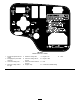
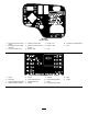
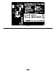
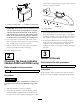

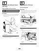
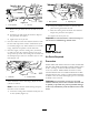


Figure4
1.Positive(+)batterycable2.Negative(–)batterycable
Important:Ifthebatteryiseverremoved,make
surethatthebatteryclampboltsareinstalled
withtheboltheadspositionedonthebottom
sideandthenutsonthetopside.Iftheclamp
boltsarereversed,theymayinterferewiththe
hydraulictubeswhenshiftingthecuttingunits.
8.CoatbothbatteryconnectionswithGrafo112X
(skinover)grease,ToroPartNo.505-47,petroleum
jelly,orlightgreasetopreventcorrosion.
9.Slidetherubberbootoverthepositiveterminalto
preventapossibleshortfromoccurring.
10.Installthebatterycover.
2
CheckingtheAngleIndicator
(Models30839and30843only)
Partsneededforthisprocedure:
1Inclinometer
Procedure
DANGER
Toreduceriskofinjuryordeathduetorollover,do
notoperatethemachineonsidehillssteeperthan
25º.
1.Parkthemachineonaat,levelsurface.
2.Verifythatthemachineislevelbyplacingahand
heldinclinometer(suppliedwiththemachine)on
theframecrossrail,bythefueltank(Figure5).The
inclinometershouldreadzerodegreeswhenviewed
fromtheoperator’sposition.
Figure5
1.Angleindicator
3.Iftheinclinometerdoesnotreadzerodegrees,
movethemachinetoalocationwhereazerodegree
readingisobtained.Theangleindicator,mountedon
themachine,shouldnowreadzerodegreesaswell.
4.Iftheangleindicatordoesnotreadzerodegrees,
loosenthetwoscrewsandnutssecuringtheangle
indicatortothemountingbracket,adjustthe
indicatortoobtainazerodegreereading,andtighten
thebolts.
3
InstallCEDecals
Partsneededforthisprocedure:
1
Warningdecal(104–5181)
Procedure
IfthismachinewillbeusedforCE,afxthewarning
decal104–5181overEnglishwarningdecal104–0484.
16