Form No. 3350–248 Debris Blower Groundsmaster 300 Series Attachment Model No. 30855—Serial No.
Write the product model and serial numbers in the space below: Contents Introduction . . . . . . . . . . . . . . . . . . . . . . . . . . . . . . . . Safety . . . . . . . . . . . . . . . . . . . . . . . . . . . . . . . . . . . . . Before Operating . . . . . . . . . . . . . . . . . . . . . . . . . While Operating . . . . . . . . . . . . . . . . . . . . . . . . . . Maintenance . . . . . . . . . . . . . . . . . . . . . . . . . . . . . Sound Pressure Level . . . . . . . . . . . . . . . . . . . . . .
• Keep all shields and safety devices in place. If a shield, safety device, or decal is illegible or damaged, repair or replace it before operation is commenced. Also tighten any loose nuts, bolts, and screws to ensure that the machine is in safe operating condition. • This product may exceed noise levels of 85 dB(A) at the operator position. Ear protectors are recommended for prolonged exposure to reduce the potential of permanent hearing damage.
• Before getting off of the seat: • At the time of manufacture, the blower conformed to safety standards in effect for riding mowers; therefore, to ensure optimum performance and safety, always purchase genuine Toro replacement parts and accessories to keep the machine all Toro. Never use “will-fit” replacement parts and accessories made by other manufacturers. Look for the Toro logo to ensure genuineness. Using unapproved replacement parts and accessories could void the warranty. D.
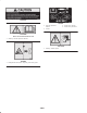
Safety and Instruction Decals Safety decals and instructions are easily visible to the operator and are located near any area of potential danger. Replace any decal that is damaged or lost. 98-3113 1. Warning—stop the engine and remove the key before leaving the machine or disconnecting the PTO shaft; read the instructions before servicing or performing maintenance. 98-3110 1. Warning—read the Operator’s Manual and receive training. 2. Warning—wear hearing protection. 3.
105-0707 99-4487 1. Read the Operator’s Manual. 2. Grease 3. Grease every 8 hours. 4. Grease every 100 hours. 105-0698 Place over decal 105–0707 for CE 1. Warning—read the Operator’s Manual. 105-0708 1. Warning—thrown objects 99-4486 1. Entanglement hazard, belt—stay away from moving parts.
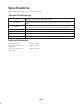
Specifications Note: Specifications and design subject to change without notice. General Specifications Fan Backward curved, cast aluminum fan. 12 blades per side, 21 in. (53 cm) outside diameter, 6-3/8 in. (16 cm) width, 34 lb. (16 kg) Fan housing 10 gauge steel face plates welded to 10 gauge wrapper. Increasing scroll from cutoff. Fan drive PTO driven A 3VX banded belt drive to fan. Final drive ratio of 1.5:1 with a over running clutch in belt drive pulley.
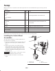
Setup Note: Use this chart as a checklist to ensure that all parts have been received. Without these parts, total setup cannot be completed. Description Qty. Use Capscrew 4 Washer 8 Nut 4 Lift arm bracket 1 Pin 1 Drive shaft 1 Capscrew 4 Nut 4 Roll pin 2 Decal 1 Apply over decal 105–0707 for CE. Operator’s Manual 1 Read before operating the machine. Parts Catalog 1 Registration card 1 Mounting the blower to the traction unit.
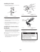
Installing the Stand 2 1. Remove the snapper pin securing the stand to the tube on the blower frame (Fig. 2). 1 1-5/8 in. (41 mm) 1 2 Figure 3 1. Lift arm Figure 2 1. Snapper pin 2. Right ball joint mount (21-3020) 2. Stand tube 2. Lower the stand. Install the pin through the upper set of holes in the stand and tube (Fig. 2). Secure the pin. 1-5/8 in. (41 mm) 3. Remove the snapper pin securing the stand to the tube on the blower frame. 1 4. Raise the stand.
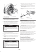
1. Remove the 5 capscrews, 6 washers, and nut securing the belt guard to the blower frame (Fig. 6). 3 2 2. Slide the drive shaft onto the traction unit PTO shaft (Fig. 6). Align the mounting holes in each shaft and slide them together. 3. Secure them with a roll pin and 2 capscrews and nuts (Fig. 6). 2 1 Figure 5 1. Right mounting bracket 2. Left mounting bracket 1 3. Lift arm bracket Figure 6 1. Belt guard 5.
Operation Note: Determine the left and right sides of the machine from the normal operating position. Adjusting the Discharge Opening Operating Tips The discharge opening is adjustable to increase or decrease air output velocity and volume. Decreasing the discharge opening size will increase the velocity. Warning 1. Loosen the discharge opening deflector mounting screws (Fig. 7). Discharged air has considerable force and could cause injury or loss of footing.
Maintenance Note: Determine the left and right sides of the machine from the normal operating position. Lubrication Idler Arm Bearing The idler arm bearing (Fig. 8) must be lubricated after every 8 hours of operation with a No. 2 Lithium-based grease. Figure 9 Drive Shaft and Guards Under normal conditions, grease the 2 drive shaft fittings after every 100 hours of use and the guards after every 8 hours of operation (Fig. 10). Use a No. 2 Lithium-based grease.
Adjusting the Blower Belt 3. When the belt stretches, adjust it as follows: A. Loosen the nuts securing the belt tensioner to the blower housing. Make sure belt is properly tensioned to ensure proper operation of the machine and unnecessary wear. Check belt frequently. B. Move the belt tensioner (Fig. 13) down until the idler spring body is extended to a length of 3-1/4 to 3-1/2 in. (83–89 mm) (Fig. 12), then tighten the nuts.
Troubleshooting Problem Possible Causes Corrective Action The fan quits turning. 1. The bolt on the PTO adapter may be sheared. 1. Replace the bolt. There is excessive vibration. 1. The bearing on the fan shaft is damaged. 1. Replace the bearings. 2. Material is built up on the fan blades. 2. Clean out any build up on the inside of the housing. 3. The RPM of the PTO shaft is too fast. 3. Reduce the PTO speed to 540 RPM. 1. The air slots are clogged with debris. 1.
Storage 1. Thoroughly clean the blower. The fan housing should be free of dirt, leaves, and debris. 2. Lubricate all grease fittings. Wipe off any excess lubricant. 3. Place a light coat of grease on the splines of the PTO adapter. 4. Tighten all fasteners.
The Toro General Commercial Products Warranty A Two-Year Limited Warranty Conditions and Products Covered The Toro Company and its affiliate, Toro Warranty Company, pursuant to an agreement between them, jointly warrant your Toro Commercial Product (“Product”) to be free from defects in materials or workmanship for two years or 1500 operational hours*, whichever occurs first.