
Operator's Manual


9
Installing the Stand
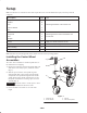
1. Remove the snapper pin securing the stand to the tube
on the blower frame (Fig. 2).
1
2
Figure 2
1. Snapper pin 2. Stand tube
2. Lower the stand. Install the pin through the upper set of
holes in the stand and tube (Fig. 2). Secure the pin.
3. Remove the snapper pin securing the stand to the tube
on the blower frame.
4. Raise the stand. Install the pin through the lower set of
holes in the stand and tube. Secure the pin.
5. Stand the blower up on the castor wheels and stand
(storage position).
Installing the Traction Unit to
the Blower
1. Remove the cutting unit or other attachment from the
traction unit. Do not remove the ball joint mounts from
the lift arms. The lift arms must be equipped with Toro
ball joint mounts, Part No. 21-3050 and 21-3020.
Note: Retain the fasteners for future installation of cutting
unit or attachment.
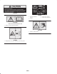
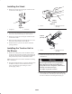
2. The right and left ball joints are properly adjusted when
the distance from the end of the lift arm nut to the
center of the ball joint grease fitting is 1-5/8 in.
(41 mm) (Fig. 3 & 4).
1-5/8 in.
(41 mm)
1
2
Figure 3
1. Lift arm 2. Right ball joint mount
(21-3020)
1-5/8 in.
(41 mm)
1
2
Figure 4
1. Lift arm 2. Left ball joint mount
(21-3050)
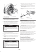
3. Position the traction unit in line with the rear of the
Debris Blower.
Since the right-hand lift arm is spring loaded to
about 100 pounds and the left-hand lift arm is
spring loaded to about 150 pounds, sudden release
of the lify arm could cause injury.
Use a helper to push the arm down.
Warning
4. Have a helper carefully push down on the right push
arm until the holes in the ball joint mount line up with
the holes in the blower mounting bracket (Fig. 5).