Form No. 3381-814 Rev A Groundsmaster® 4300-D Traction Unit Model No. 30859—Serial No. 314000001 and Up Model No. 30861—Serial No. 314000001 and Up Register at www.Toro.com.
This product complies with all relevant European directives, for details please see the separate product specific Declaration of Conformity (DOC) sheet. This manual identifies potential hazards and has safety messages identified by the safety alert symbol (Figure 1), which signals a hazard that may cause serious injury or death if you do not follow the recommended precautions. WARNING CALIFORNIA Proposition 65 Warning Figure 1 1.
Contents Fuses ....................................................................36 Drive System Maintenance .........................................37 Adjusting the Traction Drive for Neutral....................37 Adjusting the Rear Wheel Toe-in ..............................38 Cooling System Maintenance ......................................38 Removing Debris from the Cooling System ................38 Brake Maintenance ....................................................
Safe handling of fuels Safety • To avoid personal injury or property damage, use extreme care in handling gasoline. Gasoline is extremely flammable and the vapors are explosive. This machine meets or exceeds CEN standard EN 836:1997, ISO standard 5395:1990, and ANSI B71.4-2004 specifications in effect at time of production, when equipped with rear weight. Refer to the section in this manual on Installing Rear Weight. • Extinguish all cigarettes, cigars, pipes, and other sources of ignition.
• Before attempting to start the engine, disengage all blade • • • • • • • • • • • • • Look behind and down before backing up to be sure of attachment clutches, shift into neutral, and engage the parking brake. Remember there is no such thing as a safe slope. Travel on grass slopes requires particular care.
• Use full width ramps for loading machine into trailer or • If the engine stalls or loses headway and cannot make it truck. to the top of a slope, do not turn the machine around. Always back slowly, straight down the slope. • Tie the machine down securely using straps, chains, cable, • When a person or pet appears unexpectedly in or near the or ropes. Both front and rear straps should be directed down and outward from the machine mowing area, stop mowing.
Vibration Level Hand-Arm Measured vibration level for right hand = 0.34 m/s2 Measured vibration level for left hand = 0.43 m/s2 Uncertainty Value (K) = 0.5 m/s2 Measured values were determined according to the procedures outlined in EN 836. Whole Body Measured vibration level = 0.33 m/s2 Uncertainty Value (K) = 0.5 m/s2 Measured values were determined according to the procedures outlined in EN 836.
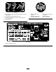
Safety and Instructional Decals Safety decals and instructions are easily visible to the operator and are located near any area of potential danger. Replace any decal that is damaged or lost. 108-5278 1. Read the Operator's Manual. 110-8973 (Affix over part no. 110–8869 for CE*) * This safety decal includes a slope warning required on the machine for compliance to the European Lawn Mower Safety Standard EN836:1997.
117–0169 1. Read the Operator's Manual. 2. Power point—10 amp 3. Head lights—10 amp 4. Power—10 amp 117–0170 5. Engine start—15 amp 6. Optional air ride seat suspension—20 amp 1. Head lights 6. Continuous variable throttle setting 8. Engine computer management B—7.5 amp 2. Engage 7. Slow 9. Engine computer management A—7.5 amp 3. Power take-off (PTO) 8. Lower cutting units 7. Engine computer management C—7.5 amp 4. Disengage 5. Fast 9. Raise cutting units 10. Read the Operator's Manual.
110-0986 106-6755 1. Press the brake pedal and parking brake pedal to set the parking brake. 1. Engine coolant under pressure. 3. Warning—do not touch the hot surface. 2. Press the brake pedal to apply the brake. 2. Explosion hazard—read the Operator's Manual. 4. Warning—read the Operator's Manual. 3. Press the traction pedal to move the machine forward. 4. Reel enabled mode 5. Transport mode 117-0168 1. Read the Operator's Manual.
Battery Symbols Some or all of these symbols are on your battery 1. Explosion hazard 6. Keep bystanders a safe distance from the battery. 2. No fire, open flame, or smoking. 7. Wear eye protection; explosive gases can cause blindness and other injuries 3. Caustic liquid/chemical burn hazard 4. Wear eye protection 8. Battery acid can cause blindness or severe burns. 9. Flush eyes immediately with water and get medical help fast. 5. Read the Operator's Manual. 10. Contains lead; do not discard.
Setup Loose Parts Use the chart below to verify that all parts have been shipped. Procedure 1 2 3 4 5 6 7 Description Use Qty. No parts required – Adjust the tire pressure. No parts required – Adjust the step height. No parts required – Adjust the control arm position. No parts required – Remove shipping blocks and pins Rear weights (quantity varies with configuration).
Figure 2 1. Step 2. Step brackets Figure 3 1. Control arm 2. Raise or lower the step to the desired height and re-secure the brackets to the frame with the 2 bolts and nuts. 3. Bolts (2) 2. Retaining brackets 2. Rotate the control arm to the desired position and tighten the 2 bolts. 3. Repeat the procedure on the other step.
5 Installing Rear Weights Parts needed for this procedure: Varies Rear weights (quantity varies with configuration). Procedure The Groundsmaster 4300–D Traction Unit complies with CEN standard EN 836:1997, ISO standard 5395:1990, and ANSI B71.4-2004 Standards when equipped with rear weights and/or 90 lb of calcium chloride ballast is added to rear wheels. Use the following charts to determine the combinations of weights required for your configuration.
Figure 4 1. Traction manifold 5. Weight(s) 2. Spacers 6. Carriage bolt 3. Bolts 4. Washers 7. Nut • Remove the 3 bolts, washers, and spacers securing the traction manifold to the bottom of the rear bumper (Figure 4a). • Position the appropriate amount of weight on the top and/or bottom of the rear bumper. • Mount the weight(s) and the traction manifold to the bumper with the 3 bolts, washers and spacers previously removed (Figure 4b).
3. Start the engine and allow it to run for 5 to 10 minutes. 4. Adjust the high idle to 2860 rpm with the cutting decks disengaged. 5. Tighten the set screw. 6. Apply adhesive into the set screw to prevent tampering. Figure 6 1. Hood latch 2. Nut 3. Rubber washer 4. Metal washer 4. Outside the hood, insert the hook end of the latch through the hole in the hood. Make sure the rubber sealing washer remains to the outer side of the hood. 5.
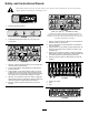
Product Overview Controls Seat Adjusting Knobs The seat adjusting lever (Figure 8) allows you to adjust the seat fore and aft. The weight adjusting knob adjusts the seat for the operator's weight. The weight gauge indicates when the seat is adjusted to the weight of the operator. The height adjusting knob adjusts the seat for the operator's height. Figure 9 1. Weight gauge 3. Height adjusting knob 4. Adjusting lever (fore and aft) 4. Brake pedal 2. Mow speed limiter 5. Parking brake 3. Spacers 6.
5 6 enabled in the mow mode. When starting the decks in the down position, this lever will turn the decks on if the PTO and the mow speed limiter are engaged. 7 8 4 9 Glow Plug Indicator Light 10 This light (Figure 10) illuminates when the glow plugs are preheating. 3 Engine Oil Pressure Warning Light 2 This light (Figure 10) indicates dangerously low engine oil pressure. Charge Indicator 1 G003956 The charge indicator (Figure 10) illuminates when the system charging circuit malfunctions.
Figure 12 1. Hydraulic filter restriction indicator Fuel Gauge Figure 14 The fuel gauge (Figure 13) shows the amount of fuel in the tank. 1. Headlight switch Power Point The power point is a 12 volt power supply for electronic devices (Figure 15). Figure 13 1. Fuel tank cap Figure 15 2. Fuel gauge 1. Power point Headlight Switch Pivot the switch downward to turn on the headlights (Figure 14).
Specifications Operation Note: Specifications and design are subject to change without notice. Transport Width 226 cm (89 inches) Width of cut 229 cm (90 inches) Length 320 cm (126 inches) Height 218 cm (86 inches) Net weight* 1,412 kg (3,114 lb) Fuel tank capacity 51 liters (13.5 US gallons) Transport speed 0–16 kph (0–10 mph) Mowing speed 0–13 kph (0–8 mph) Note: Determine the left and right sides of the machine from the normal operating position.
Checking the Cooling System Clean debris off of the screen, oil cooler, and front of the radiator daily and more often if conditions are extremely dusty and dirty. Refer to the section on Removing Debris from the Cooling System in Maintenance. The cooling system is filled with a 50/50 solution of water and permanent ethylene glycol antifreeze. Check the level of coolant in the expansion tank at the beginning of each day before starting the engine. The capacity of the cooling system is 9.5 liters (10.
quantities that can be used within 180 days to ensure fuel freshness. DANGER In certain conditions, fuel is extremely flammable and highly explosive. A fire or explosion from fuel can burn you and others and can damage property. Fuel tank capacity: 51 liters (13.5 gallons) Use summer grade diesel fuel (No. 2-D) at temperatures above 20° F (-7° C) and winter grade (No. 1-D or No. 1-D/2-D blend) below that temperature.
Pour Point, ASTM D97 -34°F to -49°F Industry Specifications: Vickers I-286-S (Quality Level), Vickers M-2950-S (Quality Level), Denison HF-0 Important: The ISO VG 46 Multigrade fluid has been found to offer optimal performance in a wide range of temperature conditions. For operation in consistently high ambient temperatures, 65° F (18° C) to 120° F (49° C), ISO VG 68 hydraulic fluid may offer improved performance.
5. Install cap/dipstick onto filler neck. Check the Torque of the Wheel Nuts Torque the wheel lug nuts to 94 to 122 N⋅m (70 to 90 ft-lb) after 1-4 hours of operation and again after 10 hours of operation. Torque every 250 hours thereafter. WARNING Failure to maintain proper torque of the wheel nuts could result in personal injury.
Jacking Points preheating is required, turn key to the Off position and then to the On/Preheat position. Repeat this process as required. 4. Run the engine at low idle speed until it warms up. Note: Use jack stands to support the machine when required. • Front—rectangular pad, under the axle tube, inside each front tire (Figure 23). Stopping the Engine 1. Move all controls to Neutral, set the parking brake, move the throttle to the low idle position and allow the engine to reach low idle speed.
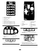
Figure 25 Figure 26 1. Rear tie down 1. Diagnostic light Understanding the Diagnostic Light Diagnostic Ace Display The machine is equipped with an electronic controller which controls most machine functions. The controller determines what function is required for various input switches (i.e. seat switch, key switch, etc.) and turns on the outputs to actuate solenoids or relays for the requested machine function.
Verifying the Interlock Switch Function If the “outputs displayed” LED is illuminated, press the toggle button, on Diagnostic ACE, to change LED to “inputs displayed”. 1. Park the machine on a level surface, lower the cutting decks, stop the engine, and engage the parking brake. 2. Remove the access panel from the side of the control arm. 3. Locate the wire harness and connectors near the controller (Figure 27).
Mowing Note: If the correct output LEDs do not illuminate, verify that the required input switches are in the necessary positions to allow that function to occur. Verify correct switch function. If the output LEDs are on as specified, but the machine does not function properly, this indicates a non-electrical problem. Repair as necessary. Start the engine and move the throttle to the Fast position.
Maintenance Note: Determine the left and right sides of the machine from the normal operating position. Recommended Maintenance Schedule(s) Maintenance Service Interval After the first hour Maintenance Procedure • Torque the wheel lug nuts to 94 to 122 N⋅m (70 to 90 ft-lb). After the first 8 hours • Check the condition and tension of the alternator belt. After the first 10 hours • Torque the wheel lug nuts to 94 to 122 N⋅m (70 to 90 ft-lb).
Daily Maintenance Checklist Duplicate this page for routine use. Maintenance Check Item For the week of: Mon. Tues. Wed. Thurs. Fri. Sat. Sun. Check the safety interlock operation. Check the brake operation. Check the engine oil and fuel level. Drain the water/fuel separator. Check the air filter restriction indicator. Check the radiator and screen for debris. Check unusual engine noises.1 Check unusual operating noises. Check the hydraulic system oil level. Check the hydraulic filter indicator.
Service Interval Chart Figure 29 CAUTION If you leave the key in the ignition switch, someone could accidently start the engine and seriously injure you or other bystanders. Remove the key from the ignition before you do any maintenance. Lubrication Greasing the Bearings and Bushings If you operate the machine under normal conditions, lubricate all grease fittings for the bearings and bushings after every 50 hours of operation with No. 2 General Purpose Lithium Base Grease.
Figure 35 • Steering cylinder ball joints (2) and rear axle (1) (Figure 36) Figure 32 • Lift arm pivot shaft (1 each) (Figure 33) Figure 33 G011614 • Rear axle tie rod (2) (Figure 34) Figure 36 • Brake pedal (1) (Figure 37) G011615 Figure 37 Figure 34 • Axle steering pivot (1) (Figure 35) 32
Engine Maintenance Servicing the Air Cleaner Check the air cleaner body for damage which could cause an air leak. Replace if damaged. Check the whole intake system for leaks, damage or loose hose clamps. Service the air cleaner filter only when the service indicator (Figure 38) requires it. Changing the air filter before it is necessary only increases the chance of dirt entering the engine when the filter is removed. Important: Be sure the cover is seated correctly and seals with the air cleaner body. 1.
3. Remove the oil filter (Figure 41). 3. Hold the injection pump lever arm against the high idle stop (Figure 42). 4. While pulling the throttle cable, to remove any slack, tighten the throttle cable connector. Note: When tightened, the cable pivot must be free to swivel on the injection pump lever arm. 5. If the throttle does not stay in position during operation, increase the torque on the locknut, used to set the friction device on the throttle lever. Figure 41 1. Oil filter 4.
Fuel System Maintenance DANGER Under certain conditions, diesel fuel and fuel vapors are highly flammable and explosive. A fire or explosion from fuel can burn you and others and can cause property damage. • Use a funnel and fill the fuel tank outdoors, in an open area, when the engine is off and is cold. Wipe up any fuel that spills. Figure 43 1. Water separator filter canister • Do not fill the fuel tank completely full.
Electrical System Maintenance Important: Before welding on the machine, disconnect both cables from the battery, both wire harness plugs from the electronic control module, and the terminal connector from the alternator to prevent damage to the electrical system. Servicing the Battery Figure 44 WARNING 2. Turn the key in the key switch to the On position and watch the fuel flow around the connector. When you observe a solid flow of fuel, turn the key to the Off position.
Drive System Maintenance Adjusting the Traction Drive for Neutral The machine must not creep when the traction pedal is released. If it does creep, adjust as follows: 1. Park the machine on a level surface, stop the engine, and lower the cutting decks to the floor. 2. Jack up the machine until all the tires are off the shop floor. Support the machine with jack stands to prevent it from falling accidentally. Figure 45 1. Fuse block 3.
Cooling System Maintenance 7. Test drive the machine to make sure it does not creep. Adjusting the Rear Wheel Toe-in 1. Rotate the steering wheel so that the rear wheels are straight ahead. Removing Debris from the Cooling System 2. Loosen the jam nut on each end of the tie rod (Figure 48). Remove debris from the screen, oil coolers, and radiator daily (clean more frequently in dirty conditions). Note: The end of the tie rod with the external groove is a left hand thread. 1.
Brake Maintenance Adjusting the Service Brakes Adjust the service brakes when there is more than 25 mm (1 inch) of free travel of the brake pedal, or when the brakes do not work effectively. Free travel is the distance the brake pedal moves before you feel braking resistance. Note: Use the wheel motor backlash to rock the drums back and forth to ensure that the drums are free prior to and after adjustment. 1.
Belt Maintenance Check the condition and tension of the alternator belt after the first day of operation and every 100 operating hours thereafter. Tensioning the Alternator Belt 1. Open the hood. 2. Check the tension of the alternator belt by depressing it (Figure 54) midway between the alternator and the crankshaft pulleys with 10 kg (22 lb) of force. 2 4 1 3 Figure 53 1. Brake cables 3. Parking brake pawl 2. Screws (2) 4. Brake detent 2.
Replacing the Hydraulic Filters Hydraulic System Maintenance The hydraulic system is equipped with a service interval indicator (Figure 56). With the engine running, view the indicator, it should be in the Green zone. When the indicator is in the Red zone, change the hydraulic filters. Changing the Hydraulic Fluid Change hydraulic fluid after every 800 operating hours, in normal conditions. If fluid becomes contaminated, contact your local Toro distributor because the system must be flushed.
WARNING Hydraulic fluid escaping under pressure can penetrate skin and cause injury. • Make sure all hydraulic fluid hoses and lines are in good condition and all hydraulic connections and fittings are tight before applying pressure to the hydraulic system. • Keep your body and hands away from pin hole leaks or nozzles that eject high pressure hydraulic fluid. • Use cardboard or paper to find hydraulic leaks.
Storage Preparing the Traction Unit 1. Thoroughly clean the traction unit, cutting decks, and engine. 2. Check the tire pressure. Inflate all traction unit tires to 83 to 103 kPa (12 to 15 psi). Figure 60 3. Check all fasteners for looseness and tighten them as necessary. 5. Turn the key to the RUN position but DO NOT start the machine. 4. Grease all grease fittings and pivot points. Wipe up any excess lubricant. 6. The current counterbalance setting will flash on the diagnostic light.
The Toro Total Coverage Guarantee A Limited Warranty Conditions and Products Covered The Toro Company and its affiliate, Toro Warranty Company, pursuant to an agreement between them, jointly warrant your Toro Commercial product (“Product”) to be free from defects in materials or workmanship for two years or 1500 operational hours*, whichever occurs first. This warranty is applicable to all products with the exception of Aerators (refer to separate warranty statements for these products).