Form No. 3369-765 Rev A Flow Divider Kit 2009 and After Groundsmaster® 4500-D/4700-D and Reelmaster® 7000-D Traction Unit Model No. 30871 Installation Instructions Safety Safety and Instructional Decals Safety decals and instructions are easily visible to the operator and are located near any area of potential danger. Replace any decal that is damaged or lost. 117-4778 117-4777 1. Flow divider 2. Lock © 2011—The Toro® Company 8111 Lyndale Avenue South Bloomington, MN 55420 1.
Installation Loose Parts Use the chart below to verify that all parts have been shipped. Description Flow divider manifold Manifold bracket Bolt (3/8 x 3-1/2 inches) Flange nut (3/8 inch) 90 degree fitting Straight fitting Hollow plug Hydraulic hose assembly D Hydraulic tube E Hydraulic tube F Hydraulic tube G Hydraulic tube H Switch Decal, operation Fuse Decal, fuse Wire harness, Reelmaster 7000-D only Jumper harness Cable tie Use Qty.
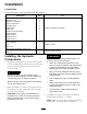
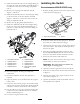
Figure 1 1. 2. 3. 4. 5. Flow divider manifold Bracket Bolt (3/8 x 3–3/4 inches) Flange nut (3/8 inch) 90 degree fitting 6. 7. 8. 9. Straight fitting 90 degree fitting Straight fitting 90 degree fitting Figure 2 1. Flow divider manifold assembly 2. 4-WD manifold 3. Vehicle frame 4. Existing fasteners C. Secure both assemblies to the frame with the fasteners removed previously. A. Mount the flow divider to the manifold bracket with a bolt (3/8 x 3-1/2 inches) and flange nut (3/8 inch). 5.
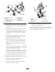
2 7. Install the new hydraulic hose D to the hydraulic pump assembly in place of the hose removed (Figure 5). 8. Route hydraulic hose D to the flow divider and connect it to the 90 degree fitting in the bottom of the manifold (Figure 5). 1 3 5 4 12 6 11 7 8 10 9 7 G010674 Figure 5 Figure 3 1. 2. 3. 4. 5. 6. 7. 8. 9. 10. 11. 12. 1. Hydraulic hose D 2.
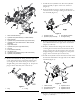
Installing the Switch 13. Install new hydraulic tube F to the straight fitting on the right side of the flow divider manifold (Figure 7). Connect the other end to the fitting on hydraulic tube C. 14. Remove the cap plug from hydraulic tube B (Figure 7, callout 3). 15. Install new hydraulic tube G to the 90 degree fitting on the front side of the flow divider manifold (Figure 7, callout 8). Connect the other end to the fitting on hydraulic tube B. 16. Remove the cap plug from hydraulic tube A. 17.
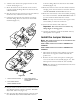
2. Insert the switch into the hole (Figure 10). Position the switch so it rocks forward to engage. 3. Clean and dry the area on the console panel, directly above the switch. Affix the flow divider operation decal to the panel. 4. Secure the ground wire ring terminal from the wire harness to the grounding block located near the fuse block. 1 Important: When routing the harness, do not pull it across sharp edges which may damage the wires. Wires must not contact any hot or moving parts.
8. Affix the fuse decal to the proper location on the console decal (Figure 11). 9. Route the harness out the bottom of the control console toward the Range Hi/Low solenoid on the 4-WD manifold. 10. Plug the relay into the connector on the wire harness. Secure the relay and harness with a cable. 11. Unplug the traction unit wire harness connector from the Range Hi/Low solenoid on the 4-WD manifold (Figure 12) it into the Range Hi/Low solenoid on the 4-WD manifold (Figure 12). 14.
Figure 15 2 1 2 1. 2WD/4WD switch connector G011677 2. New wire harness Figure 13 5. Cut the tie-wrap at the base of the harness branch going up to the deck raise/lower switches and pull back convoluted tubing about 6-8 inches. 2. Mounting screws and spacers 1. Cover 6. Find the brown/white wire and cut it 4 inches from junction (Figure 16). 3. Unplug the harness connector from the “2WD/4WD” switch (Figure 14). Figure 14 1. Harness to flow divider switch 2. 2WD/4WD Switch Figure 16 4.
Operation Operating Tips The flow divider kit enhances the traction drive performance in compromised operating conditions. Use the following information to best operate the machine with the flow divider kit installed: • The flow divider is for intermittent use in the low speed range only. The system will not allow it to operate in the high speed range. Figure 17 1. Wire splices 2.
Schematics Hydraulic Schematic (Rev.
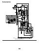
Electrical Schematic (Rev.