
Service Manual


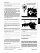


Table Of Contents
- Title Page
- Revision History
- Reader Comments
- Preface
- Table Of Contents
- 1 - Safety
- 2 - Product Records and Maintenance
- 3 - Yanmar Diesel Engine
- 4 - Hydraulic System
- Table of Contents
- Specifications
- General Information
- Hydraulic Schematics
- Hydraulic Flow Diagrams
- Special Tools
- Troubleshooting
- Testing
- Traction Circuit Charge Pressure
- Traction Circuit Relief Pressure
- Reverse Traction Circuit Reducing Valve (PR) Pressure
- Rear Traction Circuit Relief (RV) Pressure
- Piston (Traction) Pump Flow
- Cutting Deck Circuit Pressure
- Cutting Deck Circuit Relief Pressure
- Deck Motor Case Drain Leakage
- Steering Circuit Relief Pressure
- Steering Cylinder Internal Leakage
- Lift/Lower Circuit Relief Pressure
- Engine Cooling Fan Circuit
- Gear Pump Flow
- Adjustments
- Service and Repairs
- General Precautions for Removing and Installing Hydraulic System Components
- Check Hydraulic Lines and Hoses
- Priming Hydraulic Pumps
- Flush Hydraulic System
- Filtering Closed-Loop Traction Circuit
- Charge Hydraulic System
- Gear Pump
- Gear Pump Service
- Piston (Traction) Pump
- Piston (Traction) Pump Service
- Rear Traction Control Manifold
- Rear Traction Control Manifold Service
- Control Manifold Cartridge Valve Service
- HI/LOW Range Control Manifold
- Rear Axle Motor
- Front Wheel Motors
- Rear Axle and Front Wheel Motor Service
- Cutting Deck Motor
- Cutting Deck Motor Service
- Deck Control Manifold
- Deck Control Manifold Service (GM 4500-D)
- Deck Control Manifold Service (GM 4700-D)
- Steering Control Valve
- Steering Control Valve Service
- Steering Cylinder
- Steering Cylinder Service
- Engine Cooling Fan Motor
- Engine Cooling Fan Motor Service
- Fan Control Manifold
- Fan Control Manifold Service
- Lift Control Manifold
- Lift Control Manifold Service (GM 4500-D)
- Lift Control Manifold Service (GM 4700-D)
- Lift Circuit Junction Manifold
- Lift Cylinders: Decks #1, #4 and #5
- Lift Cylinders: Decks #2 and #3
- Lift Cylinders: Decks #6 and #7 (GM 4700-D)
- Lift Cylinder Service
- Hydraulic Reservoir
- Radiator and Oil Cooler Assembly
- 5 - Electrical System
- Table of Contents
- General Information
- Special Tools
- InfoCenter Display
- Troubleshooting
- Electrical System Quick Checks
- Adjustments
- Component Testing
- Ignition Switch
- Fuses
- Fusible Link Harness
- PTO Switch
- Hi/Low Speed, Engine Speed Request and Cutting Deck Lift Switches
- Headlight Switch
- Seat Switch
- Parking Brake Switch
- Cutting Deck Position Switches
- Relays with Four (4) Terminals
- Relays with Five (5) Terminals
- Traction Pedal Position Sensor
- Toro Electronic Controllers (TEC)
- Hydraulic Solenoid Valve Coils
- Piston (Traction) Pump Control Solenoid Coils
- Hydraulic Oil Temperature Sender
- Fuel Pump (Models 30873 and 30874)
- Fuel Pump (Models 30881 and 30882)
- CAN-bus Termination Resistor
- Diode Assemblies
- Resistor Assemblies
- Fan Speed Switch (Machines with Two−Post ROPS Extension Operator Fan Kit)
- Resistor Module (Machines with Two−Post ROPS Extension Operator Fan Kit)
- Service and Repairs
- 6 - Axles, Planetaries and Brakes
- Table of Contents
- Specifications
- General Information
- Adjustments
- Service and Repairs
- Brake Assembly
- Brake Inspection and Repair
- Planetary Drive Assembly
- OPH-2 Series Planetary Drive Service
- VA02 Series Planetary Drive Service
- Rear Axle Assembly
- Rear Axle Service
- Bevel Gear Case and Axle Case
- Differential Shafts
- Axle Shafts
- Input Shaft/Pinion Gear
- Differential Gear
- Pinion Gear to Ring Gear Engagement
- 7 - Chassis
- 8 - Cutting Decks
- 9 - Foldout Drawings
- Electrical Drawing Designations
- Groundsmaster 4500--D Hydraulic Schematic
- Groundsmaster 4500--D With Optional Flow Divider Kit Hydraulic Schematic
- Groundsmaster 4700--D Hydraulic Schematic
- Groundsmaster 4700--D With Optional Flow Divider Kit Hydraulic Schematic
- Electrical Schematic Groundsmaster 4500--D/4700--D Models 30881 and 30882 (Serial numbers below 315000300)
- Electrical Schematic Groundsmaster 4500--D/4700--DModels 30873 and 30874(Serial numbers below 315000300)
- Groundsmaster 4500--D/4700--D Electrical Schematic Models 30881 and 30882 (Serial Numbers 315000301 to 399999999)
- Groundsmaster 4500--D/4700--D Electrical Schematic Models 30873 and 30874 (Serial Numbers 315000301 to 399999999)
- Groundsmaster 4500--D/4700--D Electrical Schematic Models 30881 and 30882(Serial Numbers 400000000 to 403450000)
- Groundsmaster 4500--D/4700--D Electrical Schematic Models 30873 and 30874(Serial Numbers 400000000 to 403450000)
- Groundsmaster 4500--D/4700--D Electrical Schematic (Serial Numbers Serial Numbers 403450001 to 408000000)Models 30881 and 30882
- Groundsmaster 4500--D/4700--DElectrical Schematic(Serial Numbers Above 408000000)
- Groundsmaster 4500--D/4700--D Electrical Schematic (Serial Numbers Above 403450001) Models 30873 and 30874
- Electrical Schematic Groundsmaster 4500--D/4700--D Optional Operator Cab (Serial number below 399999999)
- Groundsmaster 4500--D/4700--D Electrical Schematic Optional Operator Cab (Serial Numbers Above 400000000)
- Groundsmaster 4500--D/4700--D Main Wire Harness (Serial number below 315000300)
- Groundsmaster 4500--D/4700--D Main Wire Harness (Serial Numbers 315000301 to 399999999)
- Groundsmaster 4500--D/4700--D Main Wire Harness (Serial Numbers 400000000 to 403450000)
- Groundsmaster 4500--D/4700--D Main Wire Harness (Serial Numbers Above 403450001)
- Groundsmaster 4500--D/4700--D Seat and Console Wire Harness (Serial number below 399999999)
- Groundsmaster 4500--D/4700--D Seat and Console Wire Harness (Serial Numbers 400000000 to 403450000)
- Groundsmaster 4500--D/4700--D Seat and Console Wire Harness (Serial Numbers Above 403450001)
- Groundsmaster 4500--D/4700--D Power Center Wire Harness(Serial number below 403450000)
- Groundsmaster 4500--D/4700--D Power Center Wire Harness(Serial Numbers Above 403450001)
- Deck 6 and 7 Wire Harness Groundsmaster 4700--D
- (Models 30881 and 30882) Engine Wire Harness Drawing Groundsmaster 4500--D/4700--D (Serial number below 315000000)
- Groundsmaster 4500--D/4700--D (Models 30881 and 30882) Engine Wire Harness Drawing(Serial Numbers 315000001 to 408000000)
- Groundsmaster 4500--D/4700--D(Models 30881 and 30882)Engine Wire Harness Drawing(Serial Numbers Above 408000000)
- Groundsmaster 4500--D/4700--D(Models 30881 and 30882)Engine DPF Sub--Wire Harness Drawing(Serial Numbers Above 408000000)
- (Models 30873 and 30874) Engine Wire Harness Drawing Groundsmaster 4500--D/4700--D
- Groundsmaster 4500--D/4700--D Wire Harness Diagram -- Two--Post ROPS Extension
- Groundsmaster 4500--D/4700--DPower Harness Kit -- Wiring Diagram

Groundsmaster 4500 --D/4700--D Hydraulic SystemPage 4 -- 73
Service and Repairs
General Precautions for Removing and Installing Hydraulic System Components
Before Repair or Replacement of Components
1. Before removing any parts from the hydraulic sys-
tem, park machine on a level surface, engage parking
brake, lower cutting decks and stop engine. Remove
key from the ignition switch.
2. Clean machine before disconnecting, removing or
disassembling any hydraulic components. Make sure
hydraulic components, hose connections and fittings
are cleaned thoroughly. Always keep in mind the need
for cleanliness when working on hydraulic equipment.
WARNING
Before disconnecting or performing any work
on the hydraulic system, all pressure in the sys-
tem must be relieved. See Relieving Hydraulic
System Pressure in the General Information sec-
tion in this chapter.
3. Put caps or plugs on any hydraulic lines, hydraulic fit-
tings and components left open or exposed to prevent
system contamination.
4. Put labels on disconnected hydraulic lines and
hoses for proper installation after repairs are completed.
5. Note the position of hydraulic fittings (especially el-
bow fittings) on hydraulic components before removal.
Mark parts if necessary to make sure they will be aligned
properly when installing hydraulic hoses and tubes.
After Repair or Replacement of Components
1. Check oil level in the hydraulic reservoir and add cor-
rect oil if necessary. Drain and refill hydraulic system
reservoir and change oil filters if component failure was
severe or system is contaminated (see Flush Hydraulic
System in this section).
IMPORTANT: Follow all local codes and regulations
when recycling or disposing hydraulic fluid and fil-
ters.
2. Lubricate O--rings and seals with clean hydraulic oil
before installing hydraulic components.
3. Make sure caps or plugs are removed from the hy -
draulic tubes, hydraulic fittings and components before
reconnecting.
4. Use proper tightening methods when installing hy-
draulic hoses and fittings (see Hydraulic Fitting Installa-
tion and Hydraulic Hose and Tube Installation in the
General Information section of this chapter).
5. After repairs, check control linkages and cables for
proper adjustment, binding or broken parts.
6. If piston (traction) pump, front wheel motors or rear
axle motor was removed from machine for service, fill
housing through case drain with new hydraulic oil before
starting engine. This will ensure that internal compon-
ents have adequate lubrication during initial operation.
7. After disconnecting or replacing any hydraulic com-
ponents, operate machine functions slowly until air is
out of system (see Charge Hydraulic System in this sec-
tion).
8. Before returning machine to regular operation,
check for hydraulic oil leaks. Shut off engine and correct
leaks if necessary. Check oil level in hydraulic reservoir
and add correct oil if necessary.
Hydraulic
System