
Service Manual
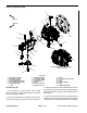
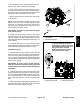
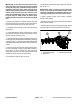
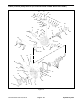
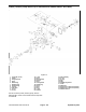
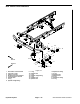

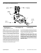
Table Of Contents
- Title Page
- Revision History
- Reader Comments
- Preface
- Table Of Contents
- 1 - Safety
- 2 - Product Records and Maintenance
- 3 - Yanmar Diesel Engine
- 4 - Hydraulic System
- Table of Contents
- Specifications
- General Information
- Hydraulic Schematics
- Hydraulic Flow Diagrams
- Special Tools
- Troubleshooting
- Testing
- Traction Circuit Charge Pressure
- Traction Circuit Relief Pressure
- Reverse Traction Circuit Reducing Valve (PR) Pressure
- Rear Traction Circuit Relief (RV) Pressure
- Piston (Traction) Pump Flow
- Cutting Deck Circuit Pressure
- Cutting Deck Circuit Relief Pressure
- Deck Motor Case Drain Leakage
- Steering Circuit Relief Pressure
- Steering Cylinder Internal Leakage
- Lift/Lower Circuit Relief Pressure
- Engine Cooling Fan Circuit
- Gear Pump Flow
- Adjustments
- Service and Repairs
- General Precautions for Removing and Installing Hydraulic System Components
- Check Hydraulic Lines and Hoses
- Priming Hydraulic Pumps
- Flush Hydraulic System
- Filtering Closed-Loop Traction Circuit
- Charge Hydraulic System
- Gear Pump
- Gear Pump Service
- Piston (Traction) Pump
- Piston (Traction) Pump Service
- Rear Traction Control Manifold
- Rear Traction Control Manifold Service
- Control Manifold Cartridge Valve Service
- HI/LOW Range Control Manifold
- Rear Axle Motor
- Front Wheel Motors
- Rear Axle and Front Wheel Motor Service
- Cutting Deck Motor
- Cutting Deck Motor Service
- Deck Control Manifold
- Deck Control Manifold Service (GM 4500-D)
- Deck Control Manifold Service (GM 4700-D)
- Steering Control Valve
- Steering Control Valve Service
- Steering Cylinder
- Steering Cylinder Service
- Engine Cooling Fan Motor
- Engine Cooling Fan Motor Service
- Fan Control Manifold
- Fan Control Manifold Service
- Lift Control Manifold
- Lift Control Manifold Service (GM 4500-D)
- Lift Control Manifold Service (GM 4700-D)
- Lift Circuit Junction Manifold
- Lift Cylinders: Decks #1, #4 and #5
- Lift Cylinders: Decks #2 and #3
- Lift Cylinders: Decks #6 and #7 (GM 4700-D)
- Lift Cylinder Service
- Hydraulic Reservoir
- Radiator and Oil Cooler Assembly
- 5 - Electrical System
- Table of Contents
- General Information
- Special Tools
- InfoCenter Display
- Troubleshooting
- Electrical System Quick Checks
- Adjustments
- Component Testing
- Ignition Switch
- Fuses
- Fusible Link Harness
- PTO Switch
- Hi/Low Speed, Engine Speed Request and Cutting Deck Lift Switches
- Headlight Switch
- Seat Switch
- Parking Brake Switch
- Cutting Deck Position Switches
- Relays with Four (4) Terminals
- Relays with Five (5) Terminals
- Traction Pedal Position Sensor
- Toro Electronic Controllers (TEC)
- Hydraulic Solenoid Valve Coils
- Piston (Traction) Pump Control Solenoid Coils
- Hydraulic Oil Temperature Sender
- Fuel Pump (Models 30873 and 30874)
- Fuel Pump (Models 30881 and 30882)
- CAN-bus Termination Resistor
- Diode Assemblies
- Resistor Assemblies
- Fan Speed Switch (Machines with Two−Post ROPS Extension Operator Fan Kit)
- Resistor Module (Machines with Two−Post ROPS Extension Operator Fan Kit)
- Service and Repairs
- 6 - Axles, Planetaries and Brakes
- Table of Contents
- Specifications
- General Information
- Adjustments
- Service and Repairs
- Brake Assembly
- Brake Inspection and Repair
- Planetary Drive Assembly
- OPH-2 Series Planetary Drive Service
- VA02 Series Planetary Drive Service
- Rear Axle Assembly
- Rear Axle Service
- Bevel Gear Case and Axle Case
- Differential Shafts
- Axle Shafts
- Input Shaft/Pinion Gear
- Differential Gear
- Pinion Gear to Ring Gear Engagement
- 7 - Chassis
- 8 - Cutting Decks
- 9 - Foldout Drawings
- Electrical Drawing Designations
- Groundsmaster 4500--D Hydraulic Schematic
- Groundsmaster 4500--D With Optional Flow Divider Kit Hydraulic Schematic
- Groundsmaster 4700--D Hydraulic Schematic
- Groundsmaster 4700--D With Optional Flow Divider Kit Hydraulic Schematic
- Electrical Schematic Groundsmaster 4500--D/4700--D Models 30881 and 30882 (Serial numbers below 315000300)
- Electrical Schematic Groundsmaster 4500--D/4700--DModels 30873 and 30874(Serial numbers below 315000300)
- Groundsmaster 4500--D/4700--D Electrical Schematic Models 30881 and 30882 (Serial Numbers 315000301 to 399999999)
- Groundsmaster 4500--D/4700--D Electrical Schematic Models 30873 and 30874 (Serial Numbers 315000301 to 399999999)
- Groundsmaster 4500--D/4700--D Electrical Schematic Models 30881 and 30882(Serial Numbers 400000000 to 403450000)
- Groundsmaster 4500--D/4700--D Electrical Schematic Models 30873 and 30874(Serial Numbers 400000000 to 403450000)
- Groundsmaster 4500--D/4700--D Electrical Schematic (Serial Numbers Serial Numbers 403450001 to 408000000)Models 30881 and 30882
- Groundsmaster 4500--D/4700--DElectrical Schematic(Serial Numbers Above 408000000)
- Groundsmaster 4500--D/4700--D Electrical Schematic (Serial Numbers Above 403450001) Models 30873 and 30874
- Electrical Schematic Groundsmaster 4500--D/4700--D Optional Operator Cab (Serial number below 399999999)
- Groundsmaster 4500--D/4700--D Electrical Schematic Optional Operator Cab (Serial Numbers Above 400000000)
- Groundsmaster 4500--D/4700--D Main Wire Harness (Serial number below 315000300)
- Groundsmaster 4500--D/4700--D Main Wire Harness (Serial Numbers 315000301 to 399999999)
- Groundsmaster 4500--D/4700--D Main Wire Harness (Serial Numbers 400000000 to 403450000)
- Groundsmaster 4500--D/4700--D Main Wire Harness (Serial Numbers Above 403450001)
- Groundsmaster 4500--D/4700--D Seat and Console Wire Harness (Serial number below 399999999)
- Groundsmaster 4500--D/4700--D Seat and Console Wire Harness (Serial Numbers 400000000 to 403450000)
- Groundsmaster 4500--D/4700--D Seat and Console Wire Harness (Serial Numbers Above 403450001)
- Groundsmaster 4500--D/4700--D Power Center Wire Harness(Serial number below 403450000)
- Groundsmaster 4500--D/4700--D Power Center Wire Harness(Serial Numbers Above 403450001)
- Deck 6 and 7 Wire Harness Groundsmaster 4700--D
- (Models 30881 and 30882) Engine Wire Harness Drawing Groundsmaster 4500--D/4700--D (Serial number below 315000000)
- Groundsmaster 4500--D/4700--D (Models 30881 and 30882) Engine Wire Harness Drawing(Serial Numbers 315000001 to 408000000)
- Groundsmaster 4500--D/4700--D(Models 30881 and 30882)Engine Wire Harness Drawing(Serial Numbers Above 408000000)
- Groundsmaster 4500--D/4700--D(Models 30881 and 30882)Engine DPF Sub--Wire Harness Drawing(Serial Numbers Above 408000000)
- (Models 30873 and 30874) Engine Wire Harness Drawing Groundsmaster 4500--D/4700--D
- Groundsmaster 4500--D/4700--D Wire Harness Diagram -- Two--Post ROPS Extension
- Groundsmaster 4500--D/4700--DPower Harness Kit -- Wiring Diagram

Rev. A
Groundsmaster 4500- D/4700- DHydraulic System Page 4 - 92
Rear Traction Co ntrol Manifold Service
1. Rear traction manifold body
2. Relief valve (port RV)
3. Pressure reducing valve (port PR)
4. #4 zero leak plug with O- ring
5. #6 zero leak plug with O- ring
6. Check valve (port CV)
7. Orifice (0.050) (port OR1)
Figure 74
25 ft- lb
(34 N- m)
115 ft- lb
(156 N- m)
20 ft- lb
(27 N- m)
50 ft- lb
(67 N- m)
1
2
4
3
5
6
7
25 ft- lb
(34 N- m)
NOTE: The ports on the rear traction manifold are
marked for easy identification of components. Example:
P2 is a piston pump connection port and RV is the loca-
tion for the relief valve (see Hydraulic Schematic in
Chapter 10 - Foldout Drawings to identify the function
of the hydraulic lines and cartridge valves at each port).
NOTE: The rear traction manifold uses several zero
leak plugs. These plugs have a tapered sealing surface
on the plug head that is designed to resist vibration in-
duced plug loosening. The zero leak plugs also have an
O- ring as a secondary seal. If zero leak plug removal is
necessary, lightly rap the plug head using a punch and
hammer before using an allen wrench to remove the
plug: the impact will allow plug r emoval with less chance
of damage to the socket head of the plug.
For rear traction manifold cartridge valve service proce-
dures, see Control Manifold Cartridge Valve Service in
this section. Refer to Figure 74 for rear traction manifold
cartridge valve and plug installation torque.
IMPORTANT: A flow control orifice (item 7) is lo-
cated beneath the hydraulic fitting in rear traction
manifold port T/OR1. If the orifice is removed from
this manifold port, make sure to label its position for
assembly purposes. When i nstalling the orifice in
the manifold, make sure that the orifice is properly
tightened in the port.