
Service Manual
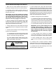

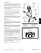


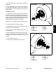

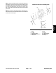

Table Of Contents
- Title Page
- Revision History
- Reader Comments
- Preface
- Table Of Contents
- 1 - Safety
- 2 - Product Records and Maintenance
- 3 - Yanmar Diesel Engine
- 4 - Hydraulic System
- Table of Contents
- Specifications
- General Information
- Hydraulic Schematics
- Hydraulic Flow Diagrams
- Special Tools
- Troubleshooting
- Testing
- Traction Circuit Charge Pressure
- Traction Circuit Relief Pressure
- Reverse Traction Circuit Reducing Valve (PR) Pressure
- Rear Traction Circuit Relief (RV) Pressure
- Piston (Traction) Pump Flow
- Cutting Deck Circuit Pressure
- Cutting Deck Circuit Relief Pressure
- Deck Motor Case Drain Leakage
- Steering Circuit Relief Pressure
- Steering Cylinder Internal Leakage
- Lift/Lower Circuit Relief Pressure
- Engine Cooling Fan Circuit
- Gear Pump Flow
- Adjustments
- Service and Repairs
- General Precautions for Removing and Installing Hydraulic System Components
- Check Hydraulic Lines and Hoses
- Priming Hydraulic Pumps
- Flush Hydraulic System
- Filtering Closed-Loop Traction Circuit
- Charge Hydraulic System
- Gear Pump
- Gear Pump Service
- Piston (Traction) Pump
- Piston (Traction) Pump Service
- Rear Traction Control Manifold
- Rear Traction Control Manifold Service
- Control Manifold Cartridge Valve Service
- HI/LOW Range Control Manifold
- Rear Axle Motor
- Front Wheel Motors
- Rear Axle and Front Wheel Motor Service
- Cutting Deck Motor
- Cutting Deck Motor Service
- Deck Control Manifold
- Deck Control Manifold Service (GM 4500-D)
- Deck Control Manifold Service (GM 4700-D)
- Steering Control Valve
- Steering Control Valve Service
- Steering Cylinder
- Steering Cylinder Service
- Engine Cooling Fan Motor
- Engine Cooling Fan Motor Service
- Fan Control Manifold
- Fan Control Manifold Service
- Lift Control Manifold
- Lift Control Manifold Service (GM 4500-D)
- Lift Control Manifold Service (GM 4700-D)
- Lift Circuit Junction Manifold
- Lift Cylinders: Decks #1, #4 and #5
- Lift Cylinders: Decks #2 and #3
- Lift Cylinders: Decks #6 and #7 (GM 4700-D)
- Lift Cylinder Service
- Hydraulic Reservoir
- Radiator and Oil Cooler Assembly
- 5 - Electrical System
- Table of Contents
- General Information
- Special Tools
- InfoCenter Display
- Troubleshooting
- Electrical System Quick Checks
- Adjustments
- Component Testing
- Ignition Switch
- Fuses
- Fusible Link Harness
- PTO Switch
- Hi/Low Speed, Engine Speed Request and Cutting Deck Lift Switches
- Headlight Switch
- Seat Switch
- Parking Brake Switch
- Cutting Deck Position Switches
- Relays with Four (4) Terminals
- Relays with Five (5) Terminals
- Traction Pedal Position Sensor
- Toro Electronic Controllers (TEC)
- Hydraulic Solenoid Valve Coils
- Piston (Traction) Pump Control Solenoid Coils
- Hydraulic Oil Temperature Sender
- Fuel Pump (Models 30873 and 30874)
- Fuel Pump (Models 30881 and 30882)
- CAN-bus Termination Resistor
- Diode Assemblies
- Resistor Assemblies
- Fan Speed Switch (Machines with Two−Post ROPS Extension Operator Fan Kit)
- Resistor Module (Machines with Two−Post ROPS Extension Operator Fan Kit)
- Service and Repairs
- 6 - Axles, Planetaries and Brakes
- Table of Contents
- Specifications
- General Information
- Adjustments
- Service and Repairs
- Brake Assembly
- Brake Inspection and Repair
- Planetary Drive Assembly
- OPH-2 Series Planetary Drive Service
- VA02 Series Planetary Drive Service
- Rear Axle Assembly
- Rear Axle Service
- Bevel Gear Case and Axle Case
- Differential Shafts
- Axle Shafts
- Input Shaft/Pinion Gear
- Differential Gear
- Pinion Gear to Ring Gear Engagement
- 7 - Chassis
- 8 - Cutting Decks
- 9 - Foldout Drawings
- Electrical Drawing Designations
- Groundsmaster 4500--D Hydraulic Schematic
- Groundsmaster 4500--D With Optional Flow Divider Kit Hydraulic Schematic
- Groundsmaster 4700--D Hydraulic Schematic
- Groundsmaster 4700--D With Optional Flow Divider Kit Hydraulic Schematic
- Electrical Schematic Groundsmaster 4500--D/4700--D Models 30881 and 30882 (Serial numbers below 315000300)
- Electrical Schematic Groundsmaster 4500--D/4700--DModels 30873 and 30874(Serial numbers below 315000300)
- Groundsmaster 4500--D/4700--D Electrical Schematic Models 30881 and 30882 (Serial Numbers 315000301 to 399999999)
- Groundsmaster 4500--D/4700--D Electrical Schematic Models 30873 and 30874 (Serial Numbers 315000301 to 399999999)
- Groundsmaster 4500--D/4700--D Electrical Schematic Models 30881 and 30882(Serial Numbers 400000000 to 403450000)
- Groundsmaster 4500--D/4700--D Electrical Schematic Models 30873 and 30874(Serial Numbers 400000000 to 403450000)
- Groundsmaster 4500--D/4700--D Electrical Schematic (Serial Numbers Serial Numbers 403450001 to 408000000)Models 30881 and 30882
- Groundsmaster 4500--D/4700--DElectrical Schematic(Serial Numbers Above 408000000)
- Groundsmaster 4500--D/4700--D Electrical Schematic (Serial Numbers Above 403450001) Models 30873 and 30874
- Electrical Schematic Groundsmaster 4500--D/4700--D Optional Operator Cab (Serial number below 399999999)
- Groundsmaster 4500--D/4700--D Electrical Schematic Optional Operator Cab (Serial Numbers Above 400000000)
- Groundsmaster 4500--D/4700--D Main Wire Harness (Serial number below 315000300)
- Groundsmaster 4500--D/4700--D Main Wire Harness (Serial Numbers 315000301 to 399999999)
- Groundsmaster 4500--D/4700--D Main Wire Harness (Serial Numbers 400000000 to 403450000)
- Groundsmaster 4500--D/4700--D Main Wire Harness (Serial Numbers Above 403450001)
- Groundsmaster 4500--D/4700--D Seat and Console Wire Harness (Serial number below 399999999)
- Groundsmaster 4500--D/4700--D Seat and Console Wire Harness (Serial Numbers 400000000 to 403450000)
- Groundsmaster 4500--D/4700--D Seat and Console Wire Harness (Serial Numbers Above 403450001)
- Groundsmaster 4500--D/4700--D Power Center Wire Harness(Serial number below 403450000)
- Groundsmaster 4500--D/4700--D Power Center Wire Harness(Serial Numbers Above 403450001)
- Deck 6 and 7 Wire Harness Groundsmaster 4700--D
- (Models 30881 and 30882) Engine Wire Harness Drawing Groundsmaster 4500--D/4700--D (Serial number below 315000000)
- Groundsmaster 4500--D/4700--D (Models 30881 and 30882) Engine Wire Harness Drawing(Serial Numbers 315000001 to 408000000)
- Groundsmaster 4500--D/4700--D(Models 30881 and 30882)Engine Wire Harness Drawing(Serial Numbers Above 408000000)
- Groundsmaster 4500--D/4700--D(Models 30881 and 30882)Engine DPF Sub--Wire Harness Drawing(Serial Numbers Above 408000000)
- (Models 30873 and 30874) Engine Wire Harness Drawing Groundsmaster 4500--D/4700--D
- Groundsmaster 4500--D/4700--D Wire Harness Diagram -- Two--Post ROPS Extension
- Groundsmaster 4500--D/4700--DPower Harness Kit -- Wiring Diagram

Groundsmaster 4500-- D/4700--D Hydraulic SystemPage 4 -- 93
Control Manifold Cartridge Valve Service
1. Make sure the control manifold is clean before re-
moving the cartridge valve from the control manifold.
2. If cartridge valve is solenoid operated, remove nut
securing solenoid coil to the cartridge valve. Carefully
slidecoiloffthevalve.
IMPORTANT: Use care w hen handling the cartridge
valve. Slight bending or distortion of the stem tube
can cause binding and malfunction. When remov-
ing cartridge valve from manifold, make sure that
deep well socket fully engages the valve base.
3. Remove cartridge valve from manifold using a deep
socket wrench. Note correct location for O--rings, seal-
ing rings and backup rings. Remove seal kit from car-
tridge valve and discard removed seals.
4. Visually inspect the port in the manifold for damage
to the sealing surfaces, damaged threads and contami-
nation.
5. Visually inspect cartridge valve for damaged sealing
surfaces and contamination.
A. Contamination may cause valves to stick or hang
up. Contamination can become lodged in small valve
orifices or seal areas causing malfunction.
B. If valve sealing surfaces appear pitted or dam-
aged, the hydraulic system may be overheating or
there may be water in the system.
CAUTION
Use goggles or other appropriate eye protection
when using compressed air for drying parts.
6. Clean cartridge valve using clean mineral spirits.
Submerge valve in clean mineral spirits to flush out con-
tamination. Particles as fine as talcum powder can affect
the operation of high pressure hydraulic valves. If car-
tridge design allows, use a wood o r plastic probe to push
the internal spool in and out 20 to 30 times to flush out
contamination. Be extremely careful not to damage car-
tridge. Use compressed air for cleaning.
7. Install the cartridge valve into the manifold:
A. Lubricate new seal kit components with clean hy-
draulic oil and install on valve. The O--rings, sealing
rings and backup rings must be arranged properly on
the cartridge valve for proper operation a nd sealing.
B. Dip assembled cartridge into clean hydraulic oil.
IMPORTANT: Use care when handling the valve
cartridge. Slight bending or distortion of the
stem tube can cause binding and malfunction.
When installing cartridge valve into manifold,
make sure that deep well socket fully engages
the valve base.
C. Thread cartridge valve carefully into manifold
port by hand until the top O--ring is met. The valve
should go into manifold port easily without binding.
D. Torque cart ridge valve using a deep socket
wrench to value identified in control manifold illustra-
tion.
8. If cartridge valve is solenoid operated, carefully
install solenoid coil to the cartridge valve. Secure coil to
valve with nut and torque nut to 60 in--lb (6.8 N--m).
9. If problems still exist after assembly, remove valve
and clean again or replace valve.
Hydraulic
System