Form No. 3389-430 Rev B 100in Rear Discharge Deck Groundsmaster® 360 Series Traction Unit Model No. 31101—Serial No. 315000001 and Up Register at www.Toro.com.
This product complies with all relevant European directives; for details, please see the separate product specific Declaration of Conformity (DOC) sheet. g000502 Figure 1 WARNING 1. Safety alert symbol CALIFORNIA Proposition 65 Warning Use of this product may cause exposure to chemicals known to the State of California to cause cancer, birth defects, or other reproductive harm. This manual uses 2 words to highlight information.
Safety • Extinguish all cigarettes, cigars, pipes, and other This machine has been designed in accordance with EN ISO 5395:2013 and ANSI B71.4-2012. • • Improper use or maintenance by the operator or owner can result in injury. To reduce the potential for injury, comply with these safety instructions and always pay attention to the safety alert symbol, which means Caution, Warning, or Danger—"personal safety instruction." Failure to comply with the instruction may result in personal injury or death.
• Keep hands and feet away from moving parts. If • Stop equipment and inspect the blades after • • • • • • • • • possible, do not make adjustments with the engine running. striking objects or if an abnormal vibration occurs. Make necessary repairs before resuming operations. Keep hands and feet away from the cutting units. Look behind and down before backing up to be sure of a clear path. Never carry passengers and keep pets and bystanders away.
• If the cutting unit discharge area ever plugs, shut the engine off before removing the obstruction. • Cut grass slopes carefully. Do not start, stop, or turn suddenly. • Do not touch the engine or muffler while the engine is running or soon after it has stopped because these areas could be hot enough to cause burns. Maintenance and Storage • Check the blade mounting bolts frequently to be sure that they are tightened to specification.
Safety and Instructional Decals Safety decals and instructions are easily visible to the operator and are located near any area of potential danger. Replace any decal that is damaged or lost. decal93-6696 93-6696 1. Stored energy hazard—read the Operator's Manual. decal119-6807 119–6807 1. Warning—no step decal120-6604 120-6604 1. Thrown object hazard—keep bystanders away from the machine. 2.
decal121-5498 121-5498 decal125-9403 125-9403 3. High 1. Height-of-cut 2.
Setup Media and Additional Parts Description Use Qty. Operator's Manual 1 Review the material and save it in an appropriate place. Parts Catalog 1 Use this catalog to reference part numbers. WARNING DANGER If you leave the key in the ignition switch, someone could accidentally start the engine and seriously injure you or other bystanders. If the engine is started and the PTO shaft is allowed to rotate, serious injury could result.
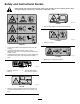
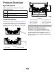
Product Overview Specifications Note: Specifications and design are subject to change without notice. Width of cut 2.54 m (100 inches) Height of cut Adjustable from 25 to 127 mm (1 to 5 inches) in 6 mm (1/4 inch) increments Net weight 358 kg (790 lb) g027696 Figure 3 Trailer Dimensions Ensure that your trailer or transport vehicle (Figure 2) has enough room to carry the deck in addition to the traction unit.
Operation Note: Determine the left and right sides of the machine from the normal operating position. 4. CAUTION Wing Decks If you leave the key in the ignition switch, someone could accidently start the engine and seriously injure you or other bystanders.
the appropriate number of 1/2 inch spacers onto the spindle shaft to get the desired height of cut; then slide the washer onto the shaft. in the higher position when operating in height of cuts lower than 64 mm (2-1/2 inches). Note: When using 25 mm (1 inch), 38 mm (1-1/2 inch), or occasionally 51 mm (2 inch) height of cut, move the skids and roller to the highest holes. 4. Secure the adjustment with the tensioning cap. Adjusting the Skid(s) 1. Disengage the PTO and set the parking brake. 2.
4. Using a short ruler, measure from the floor to the front tip of the blade. 5. Rotate the same blade tip to the rear and measure from the floor to the tip of the blade at the rear of the mower. 6. Subtract the front dimension from the rear dimension to calculate the blade pitch. 7. Adjust the U-bolt jam nuts (Figure 8) securing the rear deck chains (Figure 9) to the mower deck to raise the rear of the mower so that the blade pitch is set to 8 to 11 mm (5/16 to 7/16 inch).
Using the Transport Latches grass at this setting. Then cut the grass again using the lower, normal setting. Before transporting the machine, raise the wing decks and secure the wing deck transport latches (Figure 11). Keeping the Mower Clean Clean clippings and dirt from the underside of the mower after each use. If grass and dirt build up inside the mower, cutting quality will eventually become unsatisfactory.
Maintenance Recommended Maintenance Schedule(s) Maintenance Service Interval Maintenance Procedure After the first 2 hours • Tighten the caster wheel nuts. After the first 10 hours • Tighten the caster wheel nuts. After the first 50 hours • Change the mower deck gearbox lubricant. Before each use or daily • Lubricate the caster arm bushings. • Lubricate the caster wheel bearings. • Check the mower blades. Every 50 hours • Lubricate the grease fittings. • Tighten the caster wheel nuts.
g025301 Figure 12 1. Pull link 2. Torsion spring 4. Deck lift chain 5. Retainer pin 3. U-bolts 6.
Lubrication Service Interval: Every 50 hours The machine has grease fittings that must be lubricated regularly with #2 general-purpose, lithium-based grease. If the machine is operated under normal conditions, lubricate all bearings and bushings after every 50 hours of operation or immediately after every washing.
6. Remove the dipstick/fill plug from the top of the gearbox (Figure 20) and make sure that the lubricant is between the marks on the dipstick. g025658 Figure 18 • Spindle shaft bearings (5) (Figure 19) g014267 Figure 20 1. Fill plug and dipstick 7. 2. Drain location If the lubricant level is low, add enough lubricant until the level is between the marks on the dipstick. Note: Do not overfill the gearbox, or the gearbox may be damaged.
Servicing the Drive Belts Refer to Figure 21 for routing the drive belts appropriately. decal121-5498 Figure 21 Belt routing Servicing the Bushings in the Caster Arms The caster arms have bushings pressed into the top and bottom of the tube and after many hours of operation, the bushings will wear. To check the bushings, move the caster fork back and forth and from side to side. If the caster spindle is loose inside the bushings, the bushings are worn and must be replaced. 1. 2. 3. 4.
Servicing the Caster Wheels and Bearings 1. turns grass brown at the edges, which slows growth and increases the chance of disease. Check the blades daily for sharpness, and for any wear or damage. Sharpen the blades as necessary. If a blade is damaged or worn, replace it immediately with a genuine Toro replacement blade. Remove the locknut from the bolt holding the caster wheel assembly between the caster fork (Figure 23).
g025277 Figure 25 1. Position A g004653 Figure 24 1. Cutting edge 3. Wear/slot forming 2. Sail area 4. Crack 2. Measure here from blade to hard surface 4. Measure from a level surface to the cutting edge, position A, of the blades (Figure 25). Note this dimension. 5. Rotate the opposite ends of the blades forward. 6. Measure from a level surface to the cutting edge of the blades at the same position as in step 3 above.
WARNING Contact with a sharp blade can cause serious injury. Wear gloves or wrap sharp edges of the blade with a rag. 1. Hold the blade end using a rag or a thickly-padded glove. 2. Remove the blade bolt, the anti-scalp plate, and the blade from the spindle shaft (Figure 28). Sharpening the Blades WARNING When sharpening blade, pieces of blade could be thrown and cause serious injury. Wear proper eye protection when sharpening blades. 1. Sharpen the cutting edge at both ends of the blade (Figure 26).
Adjusting the Deck-Limit Chains 3. At the front of the deck, fully loosen the outboard serrated-flange nuts securing the 4 U-bolts (Figure 30). Use 2 deck shims Toro Part No. 138-8243 or 2 feeler gauges—0.15 mm (0.060 inch) Preparing the Deck 1. Start the engine, lower the left and right decks, shut off the engine, remove the key, and wait for all moving parts to stop. 2. At the outer decks, wipe clean the tab of the inner channel (Figure 29). g321237 Figure 30 2. U-bolt 1.
g321246 g321239 Figure 33 1. Belt cover 2. Inner-channel tab (outer deck) 3. Deck shim Note: If you are using feeler gauges, use a piece of tape to adhere a feeler gauge—0.15 mm (0.060 inch) to the tab of the inner channel (Figure 34). g321244 Figure 32 1. Deck shim 2. Inner-channel tab (outer deck) 2. 3. Belt cover Install the deck shims at the front of the deck as shown in Figure 33.
g321234 Figure 35 g321243 Figure 34 1. Inner-channel tab 2. Feeler gauge 3. 3. Front of the machine 4. Back of the machine 5. U-bolt 2. Serrated-flange nut (outboard) 6. Front of the machine 3. Pivot link 7. Serrated-flange nut (inboard) 4. Chain (limit) Start the engine, fully raise the left and right decks, shut off the engine, remove the key, and wait for all moving parts to stop. Tensioning the Chains 1. 1.
7. g321235 Figure 36 1. Deck shim (or feeler gauge) 5. Serrated-flange nut (inboard) 2. Pivot link 3. Chain (limit) 6. Front of the machine 7. Serrated-flange nut (outboard) 4. U-bolt 4. Thread the outboard serrated-flange nuts (Figure 36) and torque them to 103 to 127 N∙m (76 to 94 ft-lb). 5. Start the engine, lower adjusted deck, raise the other deck, shut off the engine, remove the key, and wait for all moving parts to stop. 6. Remove the shims or feeler gauges (Figure 37).
Declaration of Incorporation The Toro Company, 8111 Lyndale Ave. South, Bloomington, MN, USA declares that the following unit(s) conform(s) to the directives listed, when installed in accordance with the accompanying instructions onto certain Toro models as indicated on the relevant Declarations of Conformity. Model No. 31101 Serial No.
Toro General Commercial Product Warranty A Two-Year Limited Warranty Conditions and Products Covered The Toro Company and its affiliate, Toro Warranty Company, pursuant to an agreement between them, jointly warrant your Toro Commercial product (“Product”) to be free from defects in materials or workmanship for two years or 1500 operational hours*, whichever occurs first. This warranty is applicable to all products with the exception of Aerators (refer to separate warranty statements for these products).