Form No. 3425-809 Rev B 100in Rear Discharge Deck Groundsmaster® 360 Series or Serial Number 313000001 and After Groundsmaster® 7210 Traction Unit Model No. 31101—Serial No. 403330001 and Up Register at www.Toro.com.
This product complies with all relevant European directives. For details, please see the Declaration of Incorporation (DOI) at the back of this publication. WARNING CALIFORNIA Proposition 65 Warning Use of this product may cause exposure to chemicals known to the State of California to cause cancer, birth defects, or other reproductive harm. g269755 Figure 1 Model No. Serial No.
Contents Safety Safety ....................................................................... 3 General Safety ................................................... 3 Cutting Unit Safety.............................................. 3 Safety and Instructional Decals .......................... 5 Setup ........................................................................ 7 Product Overview ..................................................... 8 Specifications ..............................................
• Keep all parts in good working condition and all hardware tightened. Replace all worn or damaged decals. • Use only accessories, attachments, and replacement parts approved by Toro.
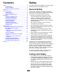
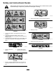
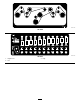
Safety and Instructional Decals Safety decals and instructions are easily visible to the operator and are located near any area of potential danger. Replace any decal that is damaged or missing. decal93-6696 93-6696 1. Stored energy hazard—read the Operator's Manual. decal119-6807 119–6807 1. Warning—no step decal120-6604 120-6604 1. Thrown object hazard—keep bystanders away from the machine. 2.
decal121-5498 121-5498 decal125-9403 125-9403 3. High 1. Height-of-cut 2.
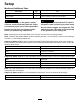
Setup Media and Additional Parts Description Use Qty. Operator's Manual 1 Review the material and save it in an appropriate place. Parts Catalog 1 Use this catalog to reference part numbers. WARNING DANGER If you leave the key in the ignition switch, someone could accidentally start the engine and seriously injure you or other bystanders. If the engine is started and the PTO shaft is allowed to rotate, serious injury could result.
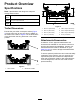
Product Overview Specifications Note: Specifications and design are subject to change without notice. Width of cut 2.54 m (100 inches) Height of cut Adjustable from 25 to 127 mm (1 to 5 inches) in 6 mm (1/4 inch) increments Net weight 358 kg (790 lb) g027696 Figure 4 Trailer Dimensions Ensure that your trailer or transport vehicle (Figure 3) has enough room to carry the deck in addition to the traction unit.
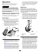
Operation Note: Determine the left and right sides of the machine from the normal operating position. 4. CAUTION Wing Decks If you leave the key in the ignition switch, someone could accidently start the engine and seriously injure you or other bystanders.
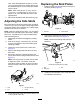
Replacing the Skid Plates units. Slide the appropriate number of 13 mm (1/2 inch) spacers onto the spindle shaft to get the desired height of cut; then slide the washer onto the shaft. 4. 1. Raise the deck wing and secure the latch pin to the latch handle (Figure 8). Note: When using 25 mm (1 inch), 38 mm (1-1/2 inch), or occasionally 51 mm (2 inch) height of cut, move the skids and roller to the highest holes. Secure the adjustment with the tensioning cap.
Adjusting the Rollers shut off the engine, engage the parking brake, and remove the key. Groundsmaster 360 Machines Mount the rollers in the lower position when operating in height of cuts higher than 64 mm (2-1/2 inches) and in the higher position when operating in height of cuts lower than 64 mm (2-1/2 inches). 1. Disengage the PTO and engage the parking brake. 2.
(Figure 13) and rotate the caster arm away from the traction unit. g025274 Figure 13 1. Caster-arm latch Important: Rotate the caster arm back to the machine before mowing. Using the Transport Latches g025273 Figure 12 1. Left rear-lift chain 2. Right rear-lift chain Before transporting the machine, raise the wing decks and secure the wing deck transport latches (Figure 14). Leveling Side to Side If the cut is uneven across the mower swath, correct it as follows: 1.
Operating Tips damage. Sharpen the blades as necessary. If a blade is damaged or worn, replace it immediately with a genuine Toro replacement blade. Refer to Servicing the Cutting Blades (page 18). Using the Fast Throttle Setting and Adjusting the Ground Speed To maintain enough power for the machine and deck while mowing, operate the engine at the fast throttle position and adjust your ground speed for conditions.
Maintenance Recommended Maintenance Schedule(s) Maintenance Service Interval Maintenance Procedure After the first 2 hours • Tighten the caster wheel nuts. After the first 10 hours • Tighten the caster wheel nuts. • Torque the blade bolts. After the first 50 hours • Change the mower deck gearbox lubricant. Before each use or daily • Lubricate the caster arm bushings. • Lubricate the caster wheel bearings. • Check the blades. After each use • Clean the cutting unit.
CAUTION If you leave the key in the ignition switch, someone could accidentally start the engine and seriously injure you or other bystanders. Remove the key from the ignition switch before you perform any maintenance. WARNING If you raise the machine using only a jack to support it while you work under the mower deck, the jack could tip, causing the mower deck to fall, crushing you or bystanders. Always secure the machine with at least 2 jack stands when you have the mower deck raised.
g025658 g014267 Figure 20 Figure 22 1. Fill plug and dipstick 2. Drain location • Spindle shaft bearings (5) (Figure 21) 7. If the lubricant level is low, add enough lubricant until the level is between the marks on the dipstick. Important: Do not overfill the gearbox and operate the mower deck; otherwise, you may damage the gearbox.
Servicing the Belts Servicing the Bushings in the Caster Arms The belts, tensioned by the spring loaded idler pulley, are very durable. However, after many hours of use, a belt will show signs of wear. Signs of a worn belt are squealing when belt is rotating, blades slipping when cutting grass, frayed edges, burn marks, and cracks. Replace the belt if any of these conditions occur. 1. 2.
Servicing the Cutting Blades Servicing the Caster Wheels and Bearings 1. Remove the locknut from the bolt holding the caster wheel assembly between the caster fork (Figure 26). Blade Safety A worn or damaged blade can break, and a piece of the blade could be thrown toward you or bystanders, resulting in serious personal injury or death. • Inspect the blade periodically for wear or damage. • Use care when checking the blades. Wrap the blades or wear gloves, and use caution when servicing the blades.
2. Grasp the end of the blade using a rag or thickly padded glove. Remove the blade bolt, anti-scalp cup, and blade from the spindle shaft (Figure 28). g025277 Figure 27 1. Position A g010555 2. Measure here from blade to hard surface Figure 28 1. Blade bolt 4. 5. 6. Measure from a level surface to the cutting edge, position A, of the blades (Figure 27). Note this dimension. Rotate the opposite ends of the blades forward.
ensure sharpness (Figure 30). The blade will remain balanced if the same amount of metal is removed from both cutting edges. during operation, and this condition is normal. As the sail wears down, the quality-of-cut will degrade somewhat, although the cutting edges are sharp. The cutting edge of the blade must be sharp so that the grass is cut rather than torn. A dull cutting edge is evident when the tips of the grass appear brown and shredded. Sharpen the cutting edges to correct this condition. 1. 2.
g321242 g321237 Figure 32 2. U-bolt 1. Serrated-flange nut (inboard) 4. At the back of the deck, fully loosen the inboard serrated-flange nuts securing the 4 U-bolts (Figure 33). g321236 Figure 31 1. Tab (inner channel—outer deck) 3. Back of the machine g321238 Figure 33 2. Front of the machine 1. U-bolt 3. At the front of the deck, fully loosen the outboard serrated-flange nuts securing the 4 U-bolts (Figure 32). 2. Serrated-flange nut (outboard) Assembling the Shim to the Deck 1.
g321246 g321239 Figure 35 1. Belt cover 2. Inner-channel tab (outer deck) 3. Deck shim Note: If you are using feeler gauges, use a piece of tape to adhere a feeler gauge—0.15 mm (0.060 inch) to the tab of the inner channel (Figure 36). g321244 Figure 34 1. Deck shim 2. Inner-channel tab (outer deck) 2. 3. Belt cover Install the deck shims at the front of the deck as shown in Figure 35.
g321234 Figure 37 g321243 Figure 36 1. Inner-channel tab 2. Feeler gauge 3. 3. Front of the machine 4. Back of the machine 5. U-bolt 2. Serrated-flange nut (outboard) 6. Front of the machine 3. Pivot link 7. Serrated-flange nut (inboard) 4. Chain (limit) Start the engine, fully raise the left and right decks, shut off the engine, remove the key, and wait for all moving parts to stop. Tensioning the Chains 1. 1.
7. Repeat steps in Assembling the Shim to the Deck (page 21) and Tensioning the Chains (page 23) for the other mower deck. Cleaning Under the Cutting Unit Service Interval: After each use Remove the grass buildup under the cutting unit daily. g321235 Figure 38 1. Deck shim (or feeler gauge) 5. Serrated-flange nut (inboard) 2. Pivot link 3. Chain (limit) 6. Front of the machine 7. Serrated-flange nut (outboard) 4. U-bolt 4.
Storage 1. Disengage the PTO, release the traction pedal to the neutral position, lower the cutting unit, move the throttle lever to the SLOW position, and engage the parking brake. 2. Always shut off the engine, and remove the key. Wait for all movement to stop and allow the machine to cool before adjusting, cleaning, storing, or repairing it. 3.
Notes:
Notes:
Declaration of Incorporation The Toro Company, 8111 Lyndale Ave. South, Bloomington, MN, USA declares that the following unit(s) conform(s) to the directives listed, when installed in accordance with the accompanying instructions onto certain Toro models as indicated on the relevant Declarations of Conformity. Model No. 31101 Serial No.
California Proposition 65 Warning Information What is this warning? You may see a product for sale that has a warning label like the following: WARNING: Cancer and Reproductive Harm—www.p65Warnings.ca.gov. What is Prop 65? Prop 65 applies to any company operating in California, selling products in California, or manufacturing products that may be sold in or brought into California.
EEA/UK Privacy Notice Toro’s Use of Your Personal Information The Toro Company (“Toro”) respects your privacy. When you purchase our products, we may collect certain personal information about you, either directly from you or through your local Toro company or dealer.
The Toro Warranty A Two-Year Limited Warranty Conditions and Products Covered The Toro Company and its affiliate, Toro Warranty Company, pursuant to an agreement between them, jointly warrant your Toro Commercial product (“Product”) to be free from defects in materials or workmanship for two years or 1500 operational hours*, whichever occurs first. This warranty is applicable to all products with the exception of Aerators (refer to separate warranty statements for these products).