Form No. 3383-938 Rev B 100in Rear Discharge Mower Groundsmaster® 360 Series Traction Unit Model No. 31101—Serial No. 314000001 and Up Register at www.Toro.com.
Contents This product complies with all relevant European directives, for details please see the separate product specific Declaration of Conformity (DOC) sheet. Safety ....................................................................... 3 Safe Operating Practices.................................... 3 Toro Mower Safety.............................................. 4 Safety and Instructional Decals .......................... 6 Setup .......................................................................
Safe Handling of Fuels Safety • To avoid personal injury or property damage, use extreme care in handling gasoline. Gasoline is extremely flammable and the vapors are explosive. This machine meets or exceeds CEN standard EN 836:1997, ISO standard 5395:1990, and ANSI B71.4-2012 specifications in effect at the time of production. • Extinguish all cigarettes, cigars, pipes, and other sources of ignition. Improper use or maintenance by the operator or owner can result in injury.
• Do not change the engine governor setting or • • • • • • • • • • • overspeed the engine. Stop on level ground, lower the cutting units, disengage drives, engage parking brake (if provided), shut off engine before leaving the operator's position for any reason. Stop equipment and inspect the blades after striking objects or if an abnormal vibration occurs. Make necessary repairs before resuming operations. Keep hands and feet away from the cutting units.
• • • • – Avoid sudden stops and starts. – When near or crossing roads, always yield the right-of-way. – Lower the cutting unit when going down slopes. The grass deflector must always be installed and in the lowest position on the side discharge cutting unit. Never operate the mower without the deflector or entire grass collector. If the cutting unit discharge area ever plugs, shut the engine off before removing the obstruction. Cut grass slopes carefully. Do not start, stop, or turn suddenly.
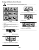
Safety and Instructional Decals Safety decals and instructions are easily visible to the operator and are located near any area of potential danger. Replace any decal that is damaged or lost. decal93-6696 93-6696 1. Stored energy hazard—read the Operator's Manual. decal119-6807 119–6807 1. Warning—no step decal120-6604 120-6604 1. Thrown object hazard—keep bystanders away from the machine. 2.
decal125-9403 125-9403 3. High 1. Height-of-cut 2.
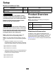
Setup Media and Additional Parts Description Use Qty. Operator's Manual 1 Review the material and save in an appropriate place Parts Catalog 1 Use to reference part numbers Product Overview WARNING If you leave the key in the ignition switch, someone could accidentally start the engine and seriously injure you or other bystanders. Specifications Note: Specifications and design are subject to Remove the key from the ignition switch before you do any maintenance. change without notice.
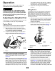
Operation Note: Determine the left and right sides of the machine from the normal operating position. 4. CAUTION Wing Decks If you leave the key in the ignition switch, someone could accidently start the engine and seriously injure you or other bystanders.
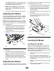
the appropriate number of 1/2 inch spacers onto the spindle shaft to get the desired height-of-cut; then slide the washer onto the shaft. in the higher position when operating in height of cuts lower than 64 mm (2-1/2 inches). Note: When using 25 mm (1 inch), 38 mm (1-1/2 inch), or occasionally 51 mm (2 inch) height of cut, move the skids and roller to the highest holes. 4. Secure the adjustment with the tensioning cap. Adjusting the Skid(s) 1. Disengage the PTO and set the parking brake. 2.
5. Leveling Side to Side Rotate the same blade tip to the rear and measure from the floor to the tip of the blade at the rear of the mower. 6. Subtract the front dimension from the rear dimension to calculate the blade pitch. 7. Adjust the U-bolt jam nuts (Figure 6) securing the rear deck chains (Figure 7) to the mower deck to raise the rear of the mower so that the blade pitch is set to 8 to 11 mm (5/16 to 7/16 inch).
Transport Latches grass at this setting. Then cut the grass again using the lower, normal setting. Before transporting the machine, raise the cutting units and secure the wing deck transport latches (Figure 9). Keeping the Mower Clean Clean clippings and dirt from the underside of the mower after each use. If grass and dirt build up inside the mower, cutting quality will eventually become unsatisfactory.
Maintenance Recommended Maintenance Schedule(s) Maintenance Service Interval Maintenance Procedure After the first 2 hours • Tighten the castor wheel nuts After the first 10 hours • Tighten the castor wheel nuts After the first 50 hours • Change the mower deck gear box lubricant Before each use or daily • Lubricate the castor arm bushings • Lubricate the castor wheel bearings • Check the mower blades.
CAUTION On the top of the mower deck are two links that connect them to the frame. Connected to these links are torsion springs that are under tension (Figure 10). If you disconnect the link the stored energy in the torsion spring will be released and could cause the links to move, damaging your hands or fingers. Be careful when removing the mower deck from the frame and secure the links before disconnecting them from the frame. g025301 Figure 10 1. Pull link 2. Torsion spring 4. Deck lift chain 5.
Lubrication Service Interval: Every 50 hours The machine has grease fittings that must be lubricated regularly with No. 2 General Purpose Lithium Base Grease. If the machine is operated under normal conditions, lubricate all bearings and bushings after every 50 hours of operation or immediately after every washing.
6. Remove the dipstick/fill plug from the top of the gear box (Figure 18) and make sure that the lubricant is between the marks on the dipstick. g025658 Figure 16 • Spindle shaft bearings (5) (Figure 17) g014267 Figure 18 1. Fill plug and dipstick 7. 2. Drain location If the lubricant level is low, add enough lubricant until the level is between the marks on the dipstick. Note: Do not over fill or the gearbox may be damaged.
Servicing the Bushings in the Castor Arms The castor arms have bushings pressed into the top and bottom of the tube and after many hours of operation, the bushings will wear. To check the bushings, move the castor fork back and forth and from side to side. If the castor spindle is loose inside the bushings, the bushings are worn and must be replaced. 1. Raise the cutting unit so that the wheels are off of the floor. Block the cutting unit so that it cannot accidentally fall. 2.
DANGER A worn or damaged blade can break, and a piece of the blade could be thrown into the operator's or bystander's area, resulting in serious personal injury or death. • Inspect the blade periodically for wear or damage. • Replace a worn or damaged blade. Inspect and check the blades every 8 hours. Before Inspecting or Servicing the Blades 1. Disengage the PTO, release the traction pedal and set the parking brake. 2.
1. Hold the blade end using a rag or thickly-padded glove. 2. Remove the blade bolt, anti-scalp plate, and blade from the spindle shaft (Figure 25). Sharpening the Blades WARNING When sharpening blade, pieces of blade could be thrown and cause serious injury. Wear proper eye protection when sharpening blades. 1. g025277 Figure 22 1. Position A 2. Measure here from blade to hard surface 4. Rotate the opposite ends of the blades forward. 5.
2. Install the anti-scalp plate and blade bolt (Figure 25). g321242 g004480 Figure 25 1. Spindle 3. Anti-scalp plate 2. Sail Area of Blade 4. Blade Bolt 3. Torque the blade bolt to 115-150 N⋅m (85-110 ft-lb). Adjusting the Deck-Limit Chains g321236 Figure 26 1. Tab (inner channel—outer deck) Use 2 deck shims Toro Part No. 138-8243 or 2 feeler gauges—0.15 mm (0.060 inch) 2. Front of the machine 3. Preparing the Deck 1.
g321246 g321237 Figure 27 2. U-bolt 1. Serrated-flange nut (inboard) 4. At the back of the deck, fully loosen the inboard serrated-flange nuts securing the 4 U-bolts (Figure 28). g321244 Figure 29 1. Deck shim 2. Inner-channel tab (outer deck) 3. Belt cover g321238 Figure 28 1. U-bolt 2. 2. Serrated-flange nut (outboard) Assembling the Shim to the Deck 1. Install the deck shims at the front of the deck as shown in Figure 29.
g321239 Figure 30 1. Belt cover 2. Inner-channel tab (outer deck) 3. Deck shim Note: If you are using feeler gauges, use a piece of tape to adhere a feeler gauge—0.15 mm (0.060 inch) to the tab of the inner channel (Figure 31). g321243 Figure 31 1. Inner-channel tab 2. Feeler gauge 3. 3. Front of the machine 4. Back of the machine Start the engine, fully raise the left and right decks, shut off the engine, remove the key, and wait for all moving parts to stop. Tensioning the Chains 1.
g321235 g321234 Figure 33 Figure 32 1. Deck shim (or feeler gauge) 5. U-bolt 1. Deck shim (or feeler gauge) 5. Serrated-flange nut (inboard) 2. Serrated-flange nut (outboard) 6. Front of the machine 2. Pivot link 3. Chain (limit) 6. Front of the machine 7. Serrated-flange nut (outboard) 3. Pivot link 7. Serrated-flange nut (inboard) 4. U-bolt 4. Chain (limit) 2. 3. 4. Thread the inboard serrated-flange nuts (Figure 32) and torque them to 103 to 127 N∙m (76 to 94 ft-lb).
7. Repeat steps in Assembling the Shim to the Deck (page 21) and Tensioning the Chains (page 22) for the other mower deck.
Notes:
Declaration of Incorporation The Toro Company, 8111 Lyndale Ave. South, Bloomington, MN, USA declares that the following unit(s) conform(s) to the directives listed, when installed in accordance with the accompanying instructions onto certain Toro models as indicated on the relevant Declarations of Conformity. Model No. 31101 Serial No.
The Toro Total Coverage Guarantee A Limited Warranty Conditions and Products Covered The Toro Company and its affiliate, Toro Warranty Company, pursuant to an agreement between them, jointly warrant your Toro Commercial product (“Product”) to be free from defects in materials or workmanship for two years or 1500 operational hours*, whichever occurs first. This warranty is applicable to all products with the exception of Aerators (refer to separate warranty statements for these products).