Form No. 3419-919 Rev B 100in Rear Discharge Deck Groundsmaster® 360 or 7210 Series Traction Unit Model No. 31101—Serial No. 400000000 and Up Register at www.Toro.com.
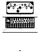
This product complies with all relevant European directives. For details, please see the Declaration of Incorporation (DOI) at the back of this publication. g000502 Figure 1 WARNING 1. Safety-alert symbol CALIFORNIA Proposition 65 Warning Use of this product may cause exposure to chemicals known to the State of California to cause cancer, birth defects, or other reproductive harm. This manual uses 2 words to highlight information.
Safety • Wear appropriate clothing, including eye protection; substantial, slip-resistant footwear; long pants, and hearing protection. Tie back long hair and do not wear loose jewelry. This machine has been designed in accordance with EN ISO 5395:2013 and ANSI B71.4-2012. • Inspect the area where the equipment is to be used and remove all objects, such as rocks, toys, and wire, that the machine can throw.
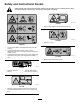
Safety and Instructional Decals Safety decals and instructions are easily visible to the operator and are located near any area of potential danger. Replace any decal that is damaged or missing. decal93-6696 93-6696 1. Stored energy hazard—read the Operator's Manual. decal119-6807 119–6807 1. Warning—no step decal120-6604 120-6604 1. Thrown object hazard—keep bystanders away from the machine. 2.
decal121-5498 121-5498 decal125-9403 125-9403 3. High 1. Height-of-cut 2.
Setup Media and Additional Parts Description Use Qty. Operator's Manual 1 Review the material and save it in an appropriate place. Parts Catalog 1 Use this catalog to reference part numbers. WARNING DANGER If you leave the key in the ignition switch, someone could accidentally start the engine and seriously injure you or other bystanders. If the engine is started and the PTO shaft is allowed to rotate, serious injury could result.
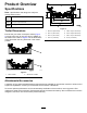
Product Overview Specifications Note: Specifications and design are subject to change without notice. Width of cut 2.54 m (100 inches) Height of cut Adjustable from 25 to 127 mm (1 to 5 inches) in 6 mm (1/4 inch) increments Net weight 358 kg (790 lb) g027696 Figure 3 Trailer Dimensions Ensure that your trailer or transport vehicle (Figure 2) has enough room to carry the deck in addition to the traction unit.
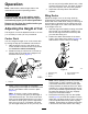
Operation Note: Determine the left and right sides of the machine from the normal operating position. 4. CAUTION Wing Decks If you leave the key in the ignition switch, someone could accidently start the engine and seriously injure you or other bystanders.
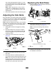
Replacing the Skid Plates units. Slide the appropriate number of 13 mm (1/2 inch) spacers onto the spindle shaft to get the desired height of cut; then slide the washer onto the shaft. 1. Raise the deck wing and secure the latch pin to the latch handle (Figure 7). Note: When using 25 mm (1 inch), 38 mm (1-1/2 inch), or occasionally 51 mm (2 inch) height of cut, move the skids and roller to the highest holes. 4. Secure the adjustment with the tensioning cap.
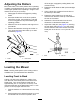
Adjusting the Rollers off the engine, engage the parking brake, and remove the key. Mount the rollers in the lower position when operating in height of cuts higher than 64 mm (2-1/2 inches) and in the higher position when operating in height of cuts lower than 64 mm (2-1/2 inches). 1. 2. Disengage the PTO and engage the parking brake. Move the throttle lever to the SLOW position, shut off the engine, remove the key, and wait for all moving parts to stop before leaving the operating position. 3.
Operating Tips Folding the Caster Arm To gain access to or from the operator area when the wing decks are folded up, release the caster arm latch (Figure 12) and rotate the caster arm away from the traction unit. g025274 Figure 12 g025273 1. Caster-arm latch Figure 11 1. Left rear-lift chain 2. Right rear-lift chain Important: Rotate the caster arm back to the machine before mowing.
Maintaining the Blade Using the Fast Throttle Setting and Adjusting the Ground Speed Maintain a sharp blade throughout the cutting season because a sharp blade cuts cleanly without tearing or shredding the grass blades. Tearing and shredding, which turns grass brown at the edges, slows growth and increases the chance of disease. Check the blades daily for sharpness, and for any wear or damage. Sharpen the blades as necessary.
Maintenance Recommended Maintenance Schedule(s) Maintenance Service Interval Maintenance Procedure After the first 2 hours • Tighten the caster wheel nuts. After the first 10 hours • Tighten the caster wheel nuts. Before each use or daily Every 50 hours • Lubricate the caster arm bushings. • Lubricate the caster wheel bearings. • Check the mower blades. • Lubricate the grease fittings. • Tighten the caster wheel nuts.
g025301 Figure 14 1. Pull link 2. Torsion spring 4. Deck-lift chain 5. Retainer pin 3. U-bolts 6. Shoulder screw Lubrication Service Interval: Every 50 hours The machine has grease fittings that must be lubricated regularly with No. 2 lithium grease. If the machine is operated under normal conditions, lubricate all bearings and bushings after every 50 hours of operation or immediately after every washing.
• Wing deck hinges (10) (Figure 18) g025837 Figure 21 g025654 Figure 18 • Folding caster arm pivot (1) (Figure 19) g025656 Figure 19 • PTO drive shaft (2) (Figure 20) g025658 Figure 20 • Spindle shaft bearings (5) (Figure 21) 15
Servicing the Drive Belts Refer to Figure 22 for routing the drive belts appropriately. decal121-5498 Figure 22 Belt routing Servicing the Bushings in the Caster Arms The caster arms have bushings pressed into the top and bottom of the tube and after many hours of operation, the bushings wear. To check the bushings, move the caster fork back and forth and from side to side. If the caster spindle is loose inside the bushings, the bushings are worn; replace them. 1.
Servicing the Caster Wheels and Bearings 1. Check the blades daily for sharpness, and for any wear or damage. Sharpen the blades as necessary. If a blade is damaged or worn, replace it immediately with a genuine Toro replacement blade. Remove the locknut from the bolt holding the caster wheel assembly between the caster fork (Figure 24). DANGER A worn or damaged blade can break, and a piece of the blade could be thrown toward you or a bystander, resulting in serious personal injury or death.
g025277 Figure 26 1. Position A g004653 Figure 25 1. Cutting edge 3. Wear/slot forming 2. Sail area 4. Crack 2. Measure here from blade to hard surface 4. Measure from a level surface to the cutting edge, position A, of the blades (Figure 26). Note this dimension. 5. Rotate the opposite ends of the blades forward. 6. Measure from a level surface to the cutting edge of the blades at the same position as in step 3 above.
WARNING Contact with a sharp blade can cause serious injury. Wear gloves or wrap sharp edges of the blade with a rag. 1. Hold the blade end using a rag or a thickly-padded glove. 2. Remove the blade bolt, the anti-scalp plate, and the blade from the spindle shaft (Figure 29). Sharpening the Blades WARNING When sharpening blade, pieces of blade could be thrown and cause serious injury. Wear proper eye protection when sharpening blades. 1. Sharpen the cutting edge at both ends of the blade (Figure 27).
Adjusting the Deck-Limit Chains 3. At the front of the deck, fully loosen the outboard serrated-flange nuts securing the 4 U-bolts (Figure 31). Use 2 deck shims Toro Part No. 138-8243 or 2 feeler gauges—0.15 mm (0.060 inch) Preparing the Deck 1. Start the engine, lower the left and right decks, shut off the engine, remove the key, and wait for all moving parts to stop. 2. At the outer decks, wipe clean the tab of the inner channel (Figure 30). g321237 Figure 31 2. U-bolt 1.
g321246 g321239 Figure 34 1. Belt cover 2. Inner-channel tab (outer deck) 3. Deck shim Note: If you are using feeler gauges, use a piece of tape to adhere a feeler gauge—0.15 mm (0.060 inch) to the tab of the inner channel (Figure 35). g321244 Figure 33 1. Deck shim 2. Inner-channel tab (outer deck) 2. 3. Belt cover Install the deck shims at the front of the deck as shown in Figure 34.
g321234 Figure 36 g321243 Figure 35 1. Inner-channel tab 2. Feeler gauge 3. 3. Front of the machine 4. Back of the machine 5. U-bolt 2. Serrated-flange nut (outboard) 6. Front of the machine 3. Pivot link 7. Serrated-flange nut (inboard) 4. Chain (limit) Start the engine, fully raise the left and right decks, shut off the engine, remove the key, and wait for all moving parts to stop. Tensioning the Chains 1. 1.
7. g321235 Figure 37 1. Deck shim (or feeler gauge) 5. Serrated-flange nut (inboard) 2. Pivot link 3. Chain (limit) 6. Front of the machine 7. Serrated-flange nut (outboard) 4. U-bolt 4. Thread the outboard serrated-flange nuts (Figure 37) and torque them to 103 to 127 N∙m (76 to 94 ft-lb). 5. Start the engine, lower adjusted deck, raise the other deck, shut off the engine, remove the key, and wait for all moving parts to stop. 6. Remove the shims or feeler gauges (Figure 38).
Notes:
Notes:
Declaration of Incorporation The Toro Company, 8111 Lyndale Ave. South, Bloomington, MN, USA declares that the following unit(s) conform(s) to the directives listed, when installed in accordance with the accompanying instructions onto certain Toro models as indicated on the relevant Declarations of Conformity. Model No. 31101 Serial No.
The Toro Warranty A Two-Year Limited Warranty Conditions and Products Covered The Toro Company and its affiliate, Toro Warranty Company, pursuant to an agreement between them, jointly warrant your Toro Commercial product (“Product”) to be free from defects in materials or workmanship for two years or 1500 operational hours*, whichever occurs first. This warranty is applicable to all products with the exception of Aerators (refer to separate warranty statements for these products).