Form No. 3439-137 Rev A 100in Rear Discharge Deck Groundsmaster® 360 Series or Serial Number 313000001 and After for a Groundsmaster® 7210 Traction Unit Model No. 31101—Serial No. 406000000 and Up Register at www.Toro.com.
This product complies with all relevant European directives. For details, please see the Declaration of Incorporation (DOI) at the back of this publication. WARNING CALIFORNIA Proposition 65 Warning Use of this product may cause exposure to chemicals known to the State of California to cause cancer, birth defects, or other reproductive harm. g269755 Figure 1 Model No. Serial No.
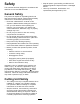
Contents Safety ....................................................................... 4 General Safety ................................................... 4 Cutting Unit Safety.............................................. 4 Safety and Instructional Decals .......................... 5 Setup ........................................................................ 7 1 Selecting the Adapter Kit.................................. 7 2 Tightening the Chains ......................................
Safety • Keep all parts in good working condition and all This machine has been designed in accordance with ANSI B71.4-2017 and EN ISO 5395. • Use only accessories, attachments, and hardware tightened. Replace all worn or damaged decals. replacement parts approved by Toro. General Safety This product is capable of amputating hands and feet and of throwing objects.
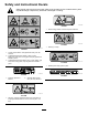
Safety and Instructional Decals Safety decals and instructions are easily visible to the operator and are located near any area of potential danger. Replace any decal that is damaged or missing. decal93-6696 93-6696 1. Stored energy hazard—read the Operator's Manual. decal119-6807 119–6807 1. Warning—no step decal120-6604 120-6604 1. Thrown object hazard—keep bystanders away from the machine. 2.
decal121-5498 121-5498 decal125-9403 125-9403 3. High 1. Height-of-cut 2.
Setup Loose Parts Use the chart below to verify that all parts have been shipped. Procedure Description 1 2 Use Qty. No parts required – Select the adapter kit. Shim 2 Tighten the chains. Media and Additional Parts Description Use Qty. Operator's Manual 1 Review the material and save it in an appropriate place. Parts Catalog 1 Use this catalog to reference part numbers.
Model Serial range 31223 314000105 and up 30539 314000117 and up All other 4WD models 314000001 and up Note: You must install Revision J or later of the Toro Diagnostic software in the vehicle controller system to operate the deck as designed. Adapter Kit, Model 31104 is for Groundsmaster® 7210 traction units in the following serial ranges: Model Serial range All 2013 and up models 313000001 and up 2 Tightening the Chains Tighten the strap until the shim hits the main mower deck. 4.
Product Overview Specifications Note: Specifications and design are subject to change without notice. Width of cut 2.54 m (100 inches) Height of cut Adjustable from 25 to 127 mm (1 to 5 inches) in 6 mm (1/4 inch) increments Net weight 358 kg (790 lb) g027696 Figure 6 Trailer Dimensions Ensure that your trailer or transport vehicle (Figure 5) has enough room to carry the deck in addition to the traction unit.
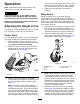
Operation Note: Determine the left and right sides of the machine from the normal operating position. 4. CAUTION Wing Decks If you leave the key in the ignition switch, someone could accidently start the engine and seriously injure you or other bystanders.
Replacing the Skid Plates units. Slide the appropriate number of 13 mm (1/2 inch) spacers onto the spindle shaft to get the desired height of cut; then slide the washer onto the shaft. 4. 1. Raise the deck wing and secure the latch pin to the latch handle (Figure 10). Note: When using 25 mm (1 inch), 38 mm (1-1/2 inch), or occasionally 51 mm (2 inch) height of cut, move the skids and roller to the highest holes. Secure the adjustment with the tensioning cap.
Adjusting the Rollers shut off the engine, engage the parking brake, and remove the key. Groundsmaster 360 Machines Mount the rollers in the lower position when operating in height of cuts higher than 64 mm (2-1/2 inches) and in the higher position when operating in height of cuts lower than 64 mm (2-1/2 inches). 1. Disengage the PTO and engage the parking brake. 2.
(Figure 15) and rotate the caster arm away from the traction unit. g025274 Figure 15 1. Caster-arm latch Important: Rotate the caster arm back to the machine before mowing. Using the Transport Latches g025273 Figure 14 1. Left rear-lift chain 2. Right rear-lift chain Before transporting the machine, raise the wing decks and secure the wing deck transport latches (Figure 16). Leveling Side to Side If the cut is uneven across the mower swath, correct it as follows: 1.
Operating Tips damage. Sharpen the blades as necessary. If a blade is damaged or worn, replace it immediately with a genuine Toro replacement blade. Refer to Servicing the Cutting Blades (page 19). Using the Fast Throttle Setting and Adjusting the Ground Speed To maintain enough power for the machine and deck while mowing, operate the engine at the fast throttle position and adjust your ground speed for conditions.
Maintenance Recommended Maintenance Schedule(s) Maintenance Service Interval Maintenance Procedure After the first 2 hours • Tighten the caster wheel nuts. After the first 10 hours • Tighten the caster wheel nuts. • Torque the blade bolts. After the first 50 hours • Change the mower deck gearbox lubricant. Before each use or daily • Lubricate the caster arm bushings. • Lubricate the caster wheel bearings. • Check the blades. After each use • Clean the cutting unit.
CAUTION If you leave the key in the ignition switch, someone could accidentally start the engine and seriously injure you or other bystanders. Remove the key from the ignition switch before you perform any maintenance. WARNING If you raise the machine using only a jack to support it while you work under the mower deck, the jack could tip, causing the mower deck to fall, crushing you or bystanders. Always secure the machine with at least 2 jack stands when you have the mower deck raised.
g025658 g014267 Figure 22 Figure 24 1. Fill plug and dipstick 2. Drain location • Spindle shaft bearings (5) (Figure 23) 7. If the lubricant level is low, add enough lubricant until the level is between the marks on the dipstick. Important: Do not overfill the gearbox and operate the mower deck; otherwise, you may damage the gearbox. g025837 Figure 23 Servicing the Mower Deck Gearbox Lubricant The gearbox is designed to operate with SAE 80W-90 gear lube.
Changing the Mower Deck Gearbox Lubricant Service Interval: After the first 50 hours Every 400 hours 1. Park the machine and cutting unit on a level surface. 2. Lower the mower deck to the 2.5 cm (1 inch) height of cut. 3. Disengage the PTO, release the traction pedal, and engage the parking brake. 4. Move the throttle lever to the SLOW position, shut off the engine, remove the key, and wait for all moving parts to stop before leaving the operating position. 5.
3. Pull the caster spindle out of the mounting tube. Allow the thrust washer and spacer(s) to remain on the bottom of the spindle. 4. Insert a pin punch into the top or bottom of the mounting tube and drive the bushing out of the tube (Figure 27). g004738 Figure 28 g004737 Figure 27 1. Caster arm tube 2. Bushings 5. Drive the other bushing out of the tube. 6. Clean the inside of the tubes to remove any dirt. 7. Apply grease to the inside and outside of the new bushings. 8.
must be replaced; refer to Checking for Bent Blades (page 20) and Removing and Installing the Blade(s) (page 20). servicing the blades. Only replace or sharpen the blades; never straighten or weld them. On multi-bladed machines, take care as rotating 1 blade can cause other blades to rotate. • WARNING Before Inspecting or Servicing the Blades 1. 2. A blade that is bent or damaged could break apart and could seriously injure or kill you or bystanders.
Inspecting and Sharpening the Blade(s) Service Interval: Before each use or daily Every 50 hours DANGER A worn or damaged blade can break, and a piece of the blade could be thrown toward you or bystanders, resulting in serious personal injury or death. g006530 Figure 31 • Inspect the blade periodically for wear or damage. 1. Cutting edge 3. Wear/slot forming 2. Curved area/sail 4. Crack WARNING • Do not try to straighten a blade that is bent.
Cleaning Under the Cutting Unit Storage 1. Disengage the PTO, release the traction pedal to the neutral position, lower the cutting unit, move the throttle lever to the SLOW position, and engage the parking brake. 2. Always shut off the engine, and remove the key. Wait for all movement to stop and allow the machine to cool before adjusting, cleaning, storing, or repairing it. 3.
Notes:
Notes:
Declaration of Incorporation The Toro Company, 8111 Lyndale Ave. South, Bloomington, MN, USA declares that the following unit(s) conform(s) to the directives listed, when installed in accordance with the accompanying instructions onto certain Toro models as indicated on the relevant Declarations of Conformity. Model No. 31101 Serial No.
California Proposition 65 Warning Information What is this warning? You may see a product for sale that has a warning label like the following: WARNING: Cancer and Reproductive Harm—www.p65Warnings.ca.gov. What is Prop 65? Prop 65 applies to any company operating in California, selling products in California, or manufacturing products that may be sold in or brought into California.
EEA/UK Privacy Notice Toro’s Use of Your Personal Information The Toro Company (“Toro”) respects your privacy. When you purchase our products, we may collect certain personal information about you, either directly from you or through your local Toro company or dealer.
The Toro Warranty Two-Year or 1,500 Hours Limited Warranty Conditions and Products Covered Parts The Toro Company and its affiliate, Toro Warranty Company, pursuant to an agreement between them, jointly warrant your Toro Commercial product (“Product”) to be free from defects in materials or workmanship for 2 years or 1,500 operational hours*, whichever occurs first. This warranty is applicable to all products with the exception of Aerators (refer to separate warranty statements for these products).