Form No. 3383-962 Rev D Adapter Kit 100in Rear Discharge Mower for 2-Wheel Drive or 2013 and Before 4-Wheel Drive Groundsmaster® 360 Traction Unit Model No. 31102 Installation Instructions WARNING CALIFORNIA Proposition 65 Warning This product contains a chemical or chemicals known to the State of California to cause cancer, birth defects, or reproductive harm.
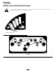
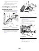
Safety Safety and Instructional Decals Safety decals and instructions are easily visible to the operator and are located near any area of potential danger. Replace any decal that is damaged or missing. decal121-5463 121-5463 1.
Installation Loose Parts Use the chart below to verify that all parts have been shipped. Description Use Qty. No parts required – Remove the existing deck.
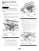
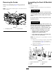
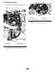
Removing the Existing Deck 2 1 Note: If the machine is not equipped with a deck, skip this procedure and proceed to Installing the Adapter Kit (page 5). CAUTION The pull link torsion springs may cause some rotation of the pull links during installation. Be careful when connecting the pull links to the machine. 1. Park the machine on a level surface with the deck in the fully raised position. Shut off the engine, engage the parking brake, and remove the key.
C. Slide the driveshaft end yoke from the gearbox shaft. D. Raise the driveshaft and tie it to the frame. 7. Slide the deck away from the machine. Installing the Adapter Kit Applying the Decals 1. Remove the existing height-of-cut decal from the height-of-cut bracket on the machine (Figure 4). g025287 Figure 5 1. Lock nut 2. New height-of-cut decal 3. Bolt 4. Washer 4.
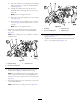
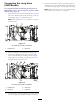
Removing the Fender Assembling the Deck Lift Manifold Block Remove the 3 self-tapping screws securing the left front fender to the machine frame (Figure 7), and remove the fender. 1. Raise the seat plate. 2. Install the orifice into the deck lift valve manifold as follows: Note: A step will be installed in place of the fender after the deck is installed.
C. Insert the orifice into the opening of the manifold block, positioning it so that the chamfered end is inward (Figure 8). D. Thread the solenoid valve into the lift valve manifold block, and torque the valve to 27 N-m (20 ft-lb). Note: Do not overtighten the nut. E. Insert the coil/spacer assembly onto the solenoid valve (Figure 8). F. Secure the coil/spacer assembly to the valve with the nut (Figure 8), and torque the nut to 7 N-m (5 ft-lb). g025598 Figure 10 Note: Do not overtighten the nut. 3.
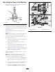
Mounting the Deck to the Machine 1. Remove the nuts securing the lift chain U-bolts to the underside of the deck (Figure 11). g025293 Figure 11 1. U-bolt 2. Nut (2) 2. Remove 1 of the top nuts from the U-bolts, insert the lift chains onto the U-bolts, and then install the top nut. g025273 Figure 12 3. Install the U-bolts to the deck with the nuts previously removed (Figure 11). 1. Left rear lift chain 4. Slide the new deck under the carrier frame of the machine.
Installing the Hoses 1. Loosely install the mid-length hydraulic hose to the outboard port of the right-hand wing cylinder (Figure 13). Note: Do not tighten the fitting. g025294 Figure 14 1. Long hose 3. Short hose 2. Deck lift valve tee fitting 4. Deck lift cylinder Note: Make sure that the hose is not twisted and does not contact any hot, sharp, or moving parts. g025303 Figure 13 1. Long hose 3. Right-hand wing cylinder 2. Mid-length hose 4. Deck lift cylinder 2.
Connecting the Long Hose (4WD Models) 5. Route the hose from the right wing cylinder along the mid-length hose, under the hydraulic tank bracket and to the new tee fitting (Figure 16) and tighten the fitting. For a simpler method of connecting the long hose on 2WD models, refer to Connecting the Long Hose (2WD Models Only) (page 11). Note: Make sure that the hose is not twisted and does not contact any hot, sharp, or moving parts. 1.
Connecting the Long Hose (2WD Models Only) 4. Connect the right wing cylinder hose to the fitting on the hydraulic line (Figure 18) and tighten the fitting. Note: Make sure that the hose is not twisted and will not contact any hot, sharp, or moving parts. This procedure does not apply to 4WD models. 1. Install the end of the long hydraulic hose to the inboard port of the right wing cylinder and tighten the fitting. 2.
Installing the Wire Harness Connecting the Pull Links to the Machine 1. Locate the fuse block and the ground block (Figure 21). 1. Secure the 2 lift cylinder hoses to the underside of the hydraulic tank with a cable tie or the R-clamp, the 3/8 x 1 inch bolt, and the sheet-metal nut supplied. Note: Make sure the hoses are not twisted and will not contact any hot, sharp, or moving parts. g025297 Figure 21 1. Fuse block 2.
g206087 Figure 24 1. Shunt wire harness Installing the Step g025299 Figure 23 1. Transmission connectors 1. Using the 3 existing fender-mounting holes, secure the front of the step to the machine with the 3 self-tapping screws previously removed (Figure 25). 2. Wire harness connectors 7. Route the wire harness to the transmission and plug the 2 mating wire harness connectors into the unplugged connectors (Figure 23). 8.
Completing the Installation 1. Install the HOC pin into the HOC bracket at the desired height of cut (Figure 26). g025302 Figure 26 1. HOC pin 2. HOC bracket 2. Check the hydraulic-oil level and replenish the oil as required; refer to the traction unit Operator’s Manual. 3. Level the cutting unit; refer to the Cutting Unit Operators Manual. 4. Lubricate the cutting unit and PTO driveshaft grease fittings; refer to the cutting unit Operator’s Manual.
Notes: