Form No. 3406-241 Rev B Adapter Kit 100in Rear Discharge Deck for 2014 and After Groundsmaster® 360 4-Wheel Drive Traction Unit Model No. 31103 Installation Instructions WARNING CALIFORNIA Proposition 65 Warning This product contains a chemical or chemicals known to the State of California to cause cancer, birth defects, or reproductive harm.
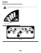
Safety Safety and Instructional Decals Safety decals and instructions are easily visible to the operator and are located near any area of potential danger. Replace any decal that is damaged or missing. decal121-5463 121-5463 1.
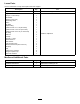
Loose Parts Use the chart below to verify that all parts have been shipped. Description Use Qty. No parts required – Remove the existing deck. Height-of-cut decal Bolt (1/2 x 2-3/4 inches) Flat washer Flange nut (1/2 inch) Belt-routing decal Orifice Tee fitting Adapter fitting Hydraulic hose—71.1 cm (28 inches) Hydraulic hose—170.2 cm (67 inches) Hydraulic hose—34.
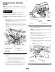
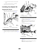
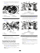
Removing the Existing Deck 2 1 Note: If the machine is not equipped with a mower deck, skip this procedure and proceed to Installing the Adapter Kit (page 5). CAUTION The pull-link torsion springs may cause some rotation of the pull links during installation. Be careful when connecting the pull links to the machine. 1. Park the machine on a level surface with the deck in the fully raised position, shut off the engine, engage the parking brake, and remove the key. G017278 g017278 Figure 2 1.
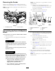
C. Slide the driveshaft end yoke from the gearbox shaft. D. Raise the driveshaft and tie it to the frame. 7. Slide the deck away from the machine. Installing the Adapter Kit Applying the Decals 1. Remove the existing height-of-cut decal from the height-of-cut bracket on the machine (Figure 4). g025287 Figure 5 1. Locknut 2. New height-of-cut decal 3. Bolt 4. Washer 4.
Removing the Fender Note: Have a drain pan or a rag available to catch the hydraulic fluid. Remove the 3 self-tapping screws securing the left, front fender to the machine frame (Figure 7) and remove the fender. A. Remove the nut securing the spacer/coil assembly to the solenoid valve in port “A” on the lift-valve-manifold block (Figure 8) and remove the spacer/coil assembly. Note: You will install a step in place of the fender after you install the deck. B.
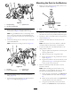
Mounting the Deck to the Machine 1. Remove the nuts securing the lift chain U-bolts to the underside of the deck (Figure 11). g025291 Figure 9 3. Hydraulic hose 1. 90-degree fitting g025293 2. Lift-valve-manifold block Figure 11 1. U-bolt 4. Remove the 90-degree fitting from the front of the manifold block (Figure 9) and discard the fitting. 2. Nut (2) 2. Remove 1 of the top nuts from the U-bolts, insert the lift chains onto the U-bolts, and then install the top nut.
Installing the Hoses 1. Loosely install the mid-length hydraulic hose to the outboard port of the right wing cylinder (Figure 13). Do not tighten the fitting. g025273 Figure 12 1. Left, rear lift chain 2. Right, rear lift chain g025303 Figure 13 8 1. Long hose 3. Right wing cylinder 2. Mid-length hose 4.
1 2. Route the hose under the hydraulic-tank bracket and to the tee fitting on the front of the manifold block (Figure 14). 2 G025597 g025597 Figure 16 As viewed from under the machine g025294 1. Hydraulic line Figure 14 1. Long hose 3. Short hose 2. Deck-lift-valve tee fitting 4. Deck-lift cylinder 2. Existing hose 2. Install a tee fitting to the hydraulic line (Figure 17). 3.
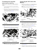
Connecting the Pull Links to the Machine Connecting the Long Hose Models 31200 and 31200A Only 1. Secure the 2 lift cylinder hoses to the underside of the hydraulic tank with a cable tie or the R-clamp, bolt (3/8 x 1 inch), and the sheet-metal nut (Figure 20). This procedure is required only on Models 31200 and 31200A. 1. Install the straight-fitting end of the long hydraulic hose to the inboard port of the right wing cylinder and tighten the fitting.
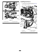
Installing the Fuse Block and the Wire Harness 1. Disconnect the battery wires from the battery posts. Important: Disconnect the negative cable from the battery post before disconnecting the positive cable. 2. Locate the 2 holes at the top of the fuse-block mounting plate (Figure 22 Figure 23). 3. Mount the fuse block to the fuse-block mounting plate with 2 washer-head screws (#10 x 3/4 inch) and nuts (#10); refer to Figure 22 and Figure 23. g037061 Figure 23 Tier 4 Yanmar Model Shown 1. Fuse block 3.
9. Connect the battery cables. Important: Connect the positive cable before connecting the negative cable. Installing the Step 1. Using the 3 existing fender mounting holes, loosely install the front of the step to the machine with the 3 self-tapping screws previously removed (Figure 26). g037063 Figure 24 1. To the main harness AUX connectors g037182 Figure 26 3. To the ground block (black wire) 1. Step 2. To the fuse block (red wire) 4. To front of center deck 2.