Form No. 3406-103 Rev C Adapter Kit 2013 and After 100in Rear Discharge Deck for Groundsmaster® 7210 Series Traction Unit Model No. 31104 Installation Instructions WARNING CALIFORNIA Proposition 65 Warning This product contains a chemical or chemicals known to the State of California to cause cancer, birth defects, or reproductive harm. Note: This adapter kit is used to mount the 100-inch Rear Discharge Deck onto Groundsmaster® 7210 Series traction units with serial numbers 313000001 and up.
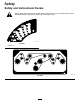
Safety Safety and Instructional Decals Safety decals and instructions are easily visible to the operator and are located near any area of potential danger. Replace any decal that is damaged or lost. decal127-4828 127-4828 1.
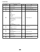
Loose Parts Use the chart below to verify that all parts have been shipped. Procedure 1 2 3 4 5 6 7 8 Description Use Qty. No parts required – Prepare the machine. No parts required – Remove the existing deck.
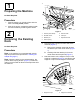
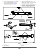
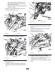
1. 1 Preparing the Machine No Parts Required Procedure 1. Park the machine on a level surface with the deck in the fully raised position. 2. Shut off the engine, engage the parking brake, and remove the key from the ignition switch. g017279 Figure 1 2 Removing the Existing Deck 1. Pull link (deck raised) 5. Deck-lift chain 2. Shoulder screw 6. Clevis pin 3. Retainer pin 7. Adjustment clevis 4. Torsion spring 2.
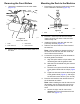
4. Start the engine and fully lower the deck. Shut off the engine and remove the key from the ignition switch. 3 Note: Lowering the deck onto furniture dollies Welding the Plates into the Frame eases the removal of the deck. Note: Elevate the front of the machine to move the deck away from the machine. 5. Remove the bolts and nuts that secure the 4 lift chains to the lift arms on the deck (Figure 1). 6. Disconnect the end yoke of the PTO driveshaft from the deck gearbox shaft as follows: A.
2. Sand off the paint in the areas to be welded to achieve good weld penetration (Figure 4). 3. Clamp the plates to the frame and weld according to the diagrams in Figure 4. 4. 5. After the frame has cooled, touch up the exposed metal parts with black touch-up paint (Toro Part No. 112-0176 or 500-41). Connect the battery cables to the battery posts. Important: Connect the positive cable before connecting the negative cable. g029623 Figure 4 1. Long plate 3.
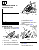
4 Installing the Adapter Kit Parts needed for this procedure: 1 Height-of-cut decal 1 Bolt 1 Washer 1 Locknut 1 Belt-routing decal 1 Orifice disc 2 Tee fitting 1 Hydraulic hose—53 cm (21 inches) long 1 Hydraulic hose—43 cm (17 inches) long 1 Deck wire harness 1 Fuse block and fuse 1 Ground block 2 Screw 2 Nut 1 Jumper strip 1 Shunt wire harness g026553 Figure 6 1. Locknut (1/2 inch) 3. Bolt (1/2 x 2-3/4 inches) 2. New height-of-cut decal 4. Washer 4.
Assembling the Deck-Lift Manifold WARNING Hydraulic fluid escaping under pressure can penetrate skin and cause injury. • Make sure that all hydraulic fluid hoses and lines are in good condition and all hydraulic connections and fittings are tight before applying pressure to the hydraulic system. g026611 • Seek immediate medical attention if fluid is injected into skin. Figure 9 1. Coil 2.
2. I. Secure the coil/spacer assembly to the valve with the nut (Figure 10) and torque the nut to 7 N∙m (5 ft-lb). J. Install the lift-valve manifold using the bolts removed in step C. Remove the hose from the rear port on the deck-lift cylinder (Figure 11). g026618 Figure 13 1. Short hose g026616 Figure 11 1. Rear port 3. 2. Long hose 6. Install the other end of the short hose to the tee fitting on the rear port on the deck-lift cylinder (Figure 13). 7.
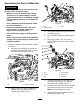
Mounting the Deck to the Machine Removing the Front Rollers 1. 1. Remove the hardware from the roller shafts (Figure 15). Remove the nuts securing the lift chain U-bolts to the underside of the deck (Figure 16). g025293 Figure 16 1. U-bolt 2. Remove 1 of the top nuts from the U-bolts, install a lift chain onto each U-bolt, and then install the top nuts. 3. Install the U-bolts to the deck with the nuts previously removed (Figure 16). 4. Slide the new deck under the carrier frame of the machine.
Connecting the Pull Links to the Machine CAUTION The pull-link torsion springs may cause some rotation of the pull links during installation, which could pinch you and result in injury. Be careful when connecting the pull links to the machine. 1. g026642 Figure 17 Note: Place a wood block or similar shim under 1. Right, rear lift chain B. Start the engine and fully raise the deck. Shut off the engine and remove the key from the ignition switch. each link to hold it in the raised position (Figure 19).
Installing the Deck Wire Harness 1. Disconnect the battery cables from the battery posts. Important: Disconnect the negative cable form the battery post before disconnecting the positive cable. 2. Locate the fuse block (Figure 20). g036544 Figure 21 1. New fuse block B. Install the ground block in the location shown in Figure 22. g026664 Figure 20 1. Fuse block 3. Install the new deck wire harness as follows: A. Attach the red wire to an available connector on the fuse block.
D. Locate the black wire in the main deck harness and attach it to 1 side of the jumper strip on the ground block (Figure 22). E. Attach the black wire in the deck harness to the other side of the jumper strip (Figure 22). Note: Leave the deck wire harness connectors unplugged. Perform this after you connect the relays to the relay bracket in 5 Installing the Timer (page 13). 4. Unplug the connectors at the front of the transmission near the oil filter (Figure 23). 5.
2. 5 Install the relay bracket on the underside of the tank support and bracket with the existing bolt and nut (Figure 27). Installing the Timer Parts needed for this procedure: 1 Relay bracket (with timer installed) 5 Relay 2 Bolt (10-24 x 0.56 inch) 2 Locknut 1 Lift-delay wire harness Procedure Note: This timer sets a 3 to 4 second delay which disables the user from raising the deck before the blades stop.
Important: Secure the excess harness away from any hot, sharp, or moving parts. 6 Installing the Right Fender Parts needed for this procedure: g036409 C. Fender mount 1 Right fender 2 Thread-forming screw (5/16 x 5/8 inch) 2 Bolt (1/4 x 5/8 inch) 2 Nut (1/4 inch) Procedure Figure 29 1. 3. Black wire 4. Red wire 1. Ground block 2. Terminal screw 1 Route the lift-delay harness toward the previously installed relay bracket and plug the 3 timer connectors into the timer (Figure 30).
g029559 Figure 32 1. Hose clamp g029561 Figure 34 2. Bolt 1. Mark here 5. Insert the bottom of the hose clamp through the slot in the top of the fender mount (Figure 33). 9. Remove the bolt and nut securing the clamp and fender mount to the frame. g029560 Figure 33 g029562 Figure 35 1. Fender mount 1. Drill here 6. Loosely mount the hose clamp and fender mount to the frame channel with the bolt previously removed. 10. 7. Position the frame mount horizontally on the frame channel.
7 Installing the Left Fender Parts needed for this procedure: 14. Loosely mount the side of the right fender to the fender mount with 2 bolts (1/4 x 5/8 inch) and 2 nuts (1/4 inch) as shown in Figure 37. 2 Nut (3/8 inch) 2 Bolt (3/8 x 3/4 inch) 1. Disconnect the cable from the negative terminal of the battery. 2. Disconnect the cable from the positive terminal of the battery. 3. Remove the carriage bolt, washer, battery hold-down, and nut securing the battery (Figure 38). 1.
Note: Verify that the tires do not rub on the fenders when you drive the machine. g029566 Figure 39 1. Fuel-tank bracket 7. 8. 2. Left fender Position the battery onto the battery platform. Loosely mount the battery to the battery platform with the carriage bolt, hold-down, washer, and nut that you previously removed (Figure 40). g029567 Figure 40 9. 10. 11. 12. 13. Tighten the fasteners. Connect the positive battery cable to the battery, and then connect the negative battery cable to the battery.
8 Completing the Installation No Parts Required Procedure 1. Install the height-of-cut pin into the height-of-cut bracket at the desired height of cut (Figure 41). g026556 Figure 41 1. Height-of-cut pin 2. 3. 4. 5. 2. Height-of-cut bracket Check the hydraulic-fluid level and replenish the fluid as required; refer to the machine Operator’s Manual. Level the cutting unit; refer to the cutting unit Operator’s Manual.